
Electronics Fundamentals: Circuits, Devices & Applications
8th Edition
ISBN: 9780135072950
Author: Thomas L. Floyd, David Buchla
Publisher: Prentice Hall
expand_more
expand_more
format_list_bulleted
Videos
Textbook Question
Chapter 13, Problem 15P
Determine
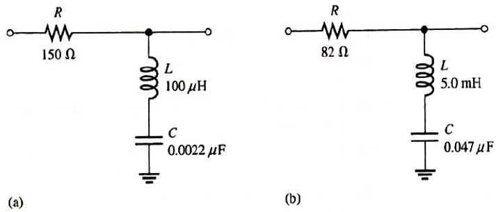
FIGURE 13-71
Expert Solution & Answer
Want to see the full answer?
Check out a sample textbook solution
Students have asked these similar questions
2. Determine the output level (maximum positive or maxiimum negative)) for each comparator in
Figure 13-60.
7 Vo
Vaur
SV=
(C)
IGURE 13-60
2. Determine the output level (maximum positive or maximum negative) for each comparator in
Figure 13-60.
+1 Vo
+7 Vo
VOUT
VOUT
VOUT
+2 Vo-
5 V
(a)
(b)
(c)
8. Determine the output voltage waveform in Figure 13-64
D2
4.7 V
4.7 V
+3 V
R1
47 k
-3 V
our
R
47 k!
Ry
10 k
+
Chapter 13 Solutions
Electronics Fundamentals: Circuits, Devices & Applications
Ch. 13 - A series RLC circuit can have a higher voltage...Ch. 13 - The impedance of a series RLC circuit is dependent...Ch. 13 - Above the resonant frequency, series resonant...Ch. 13 - Prob. 4TFQCh. 13 - Prob. 5TFQCh. 13 - The upper and lower cutoff frequencies of a...Ch. 13 - Prob. 7TFQCh. 13 - The Q of a band-pass filter does not affect the...Ch. 13 - Prob. 9TFQCh. 13 - Prob. 10TFQ
Ch. 13 - Prob. 1STCh. 13 - The phase angle of a series RLC circuit at...Ch. 13 - The impedance at the resonant frequency of a...Ch. 13 - In a series RLC circuit that is operating below...Ch. 13 - Prob. 5STCh. 13 - Prob. 6STCh. 13 - Prob. 7STCh. 13 - Prob. 8STCh. 13 - Prob. 9STCh. 13 - Prob. 10STCh. 13 - Prob. 11STCh. 13 - Prob. 12STCh. 13 - A certain series RLC circuit operates at a...Ch. 13 - Find the impedance in Figure 13-66.Ch. 13 - If the frequency of the source voltage in Figure...Ch. 13 - For the circuit in figure 13-66, find Itot,VR,VL,...Ch. 13 - Draw the voltage phasor diagram for the circuit in...Ch. 13 - Analyze the circuit in Figure 13-67 for the...Ch. 13 - For the circuit in Figure 13-66, is the resonant...Ch. 13 - For the circuit in Figure 13-68, determine the...Ch. 13 - Find XL,XC,Z, and I at the resonant frequency in...Ch. 13 - A certain series resonant circuit has a maximum...Ch. 13 - For the RLC circuit in Figure 13-69, determine the...Ch. 13 - What is the value of the current at the half-power...Ch. 13 - Determine the resonant frequency for each filter...Ch. 13 - FIGURE 13-70 Assuming that the coils in Figure...Ch. 13 - Determine fr and BW for each filter in Figure...Ch. 13 - Find the total impedance of the circuit in Figure...Ch. 13 - Is the circuit in Figure 13-72 capacitive or...Ch. 13 - For the circuit in Figure 13-72, find all the...Ch. 13 - Find the total impedence for the circuit in Figure...Ch. 13 - What is the impedance of an ideal parallel...Ch. 13 - Prob. 21PCh. 13 - How much current is drawn from the source in...Ch. 13 - At resonance, XL=2K and RW=25 in a parallel...Ch. 13 - If the lower cutoff frequency is 2400 Hz and the...Ch. 13 - In a certain resonant circuit, the power to the...Ch. 13 - What values of L and C should be used in a tank...Ch. 13 - Prob. 27PCh. 13 - A parallel resonant band-stop filter is needed to...Ch. 13 - Prob. 29PCh. 13 - Prob. 30PCh. 13 - Prob. 31PCh. 13 - Determine whether there is a value of C that will...Ch. 13 - If the value of C is 0.22F, how much current is...Ch. 13 - Determine the resonant frequencies in Figure 13-77...Ch. 13 - Prob. 35PCh. 13 - Prob. 36PCh. 13 - Prob. 37PCh. 13 - Prob. 39PCh. 13 - Prob. 40PCh. 13 - Prob. 41PCh. 13 - Open file P13-42. Determine if there is a fault...Ch. 13 - Prob. 43P
Knowledge Booster


Learn more about
Need a deep-dive on the concept behind this application? Look no further. Learn more about this topic, electrical-engineering and related others by exploring similar questions and additional content below.Similar questions
- 18. A triangular waveform with a peak-to-peak voltage of 2 V and a period of I ms is applied to the differentiator in Figure 13–70(a). What is the output voltage? 洋SV 15 k) 10 µF 10 10 kM 0.047 µF (b) () Aetivate Wndew FIGURE 13-70arrow_forwardH: A 4V peak sine wave is fed to the circuit and a 1V peak sine wave results. Determine the gain in units of db. Va R1 ww Vb T C1 Gain Frequencyarrow_forwardWhat is the lower cutoff frequency due to C, C2 and C3 for circuit in figure 1? Assume re = 4.5 ohm and Beta = 200. 10ka 10 F 2N3904 10 pF 100 Ra 47 ka 1330a 47 pFarrow_forward
- For each of the cascaded counter configurations in Figure below, determine the frequency of the waveform at each point indicated by a circled number, and determine the overall modulus. I kHz DIV 4 DIV 8 DIV 2 (a) DIV 10 DIV 10 DIV 10 DIV 2 100 kHz (b)arrow_forwardQuestion 2 Vout What is the gain, , of the given circuit? Vin 15- j9 N Vin 9 + j2 N Vout O 0.70Z - 14.7° O 1.90Z - 43.5° O 0.53/43.5 O 0.37/28.8°arrow_forwardA step up chopper delivers a 2A current to the 10ohm load. The input voltage is 100V, L=1mH with chopper frequency of 10kHz. Determine the maximum and minimum current at the outputarrow_forward
- series circuit resiarrow_forwardExercise: Consider the series RLC circuit of Figure 1 with the source a 1-kHz sinusoid having an amplitude of 5 V. Regard the source voltage as having zero phase. Calculate the amplitude and phase (in degrees) of the following quantities: the voltage across the resistor, the voltage across the inductor, and the voltage across the capacitorarrow_forwardResonent circuitarrow_forward
- Q7/ Draw the output waveform of the differentiator whose R=1M, and C=100µf for the input waveform shown below (the duty cycle is 50%). VIN 10μsecond Your answer Q8/ Please send your answers in a single pdf file ONLY * 1 Add file Page 1 of 1 Submit Alouar oihmit n uerde threushCaal. Formearrow_forward17. If a signal voltage of 10 mV rms is applied to each amplifier in Figure 12–66, what are the out- put voltages and what is their phase relationship with inputs? 1.0 MO R 47 karrow_forwardDetermine Rc, RE, RB, VCE0, & VB 12V Ic = 2 mA Ro RB 7.6 V B = 80 B VCE E 2.4 V REarrow_forward
arrow_back_ios
SEE MORE QUESTIONS
arrow_forward_ios
Recommended textbooks for you
 Introductory Circuit Analysis (13th Edition)Electrical EngineeringISBN:9780133923605Author:Robert L. BoylestadPublisher:PEARSON
 Delmar's Standard Textbook Of ElectricityElectrical EngineeringISBN:9781337900348Author:Stephen L. HermanPublisher:Cengage Learning
 Programmable Logic ControllersElectrical EngineeringISBN:9780073373843Author:Frank D. PetruzellaPublisher:McGraw-Hill Education
 Fundamentals of Electric CircuitsElectrical EngineeringISBN:9780078028229Author:Charles K Alexander, Matthew SadikuPublisher:McGraw-Hill Education
 Electric Circuits. (11th Edition)Electrical EngineeringISBN:9780134746968Author:James W. Nilsson, Susan RiedelPublisher:PEARSON
 Engineering ElectromagneticsElectrical EngineeringISBN:9780078028151Author:Hayt, William H. (william Hart), Jr, BUCK, John A.Publisher:Mcgraw-hill Education,
Introductory Circuit Analysis (13th Edition)
Electrical Engineering
ISBN:9780133923605
Author:Robert L. Boylestad
Publisher:PEARSON
Delmar's Standard Textbook Of Electricity
Electrical Engineering
ISBN:9781337900348
Author:Stephen L. Herman
Publisher:Cengage Learning
Programmable Logic Controllers
Electrical Engineering
ISBN:9780073373843
Author:Frank D. Petruzella
Publisher:McGraw-Hill Education
Fundamentals of Electric Circuits
Electrical Engineering
ISBN:9780078028229
Author:Charles K Alexander, Matthew Sadiku
Publisher:McGraw-Hill Education
Electric Circuits. (11th Edition)
Electrical Engineering
ISBN:9780134746968
Author:James W. Nilsson, Susan Riedel
Publisher:PEARSON
Engineering Electromagnetics
Electrical Engineering
ISBN:9780078028151
Author:Hayt, William H. (william Hart), Jr, BUCK, John A.
Publisher:Mcgraw-hill Education,
Inductors Explained - The basics how inductors work working principle; Author: The Engineering Mindset;https://www.youtube.com/watch?v=KSylo01n5FY;License: Standard Youtube License