
Electronics Fundamentals: Circuits, Devices & Applications
8th Edition
ISBN: 9780135072950
Author: Thomas L. Floyd, David Buchla
Publisher: Prentice Hall
expand_more
expand_more
format_list_bulleted
Videos
Textbook Question
Chapter 13, Problem 4P
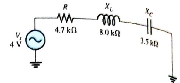
For the circuit in figure 13-66, find
Expert Solution & Answer
Want to see the full answer?
Check out a sample textbook solution
Students have asked these similar questions
8. Determine the output voltage waveform in Figure 13-64.
D,
D2
+3 V
4.7 V
4.7 V
R1
47 k2
O V qut
-3 V
R2
47 kN
R3
10 kN
13. Find the output voltage when the input voltages shown in Figure 13-67 are applied to the scal-
ing adder. What is the current through R?
FIGURE 13-67
R1
Rp
10 k(2
R2
VIN=+3 Vo- W
33 k2
10 kM
R3
OVOUT
VIN3 = +3 Vo
91 k2
R4
VINA = 16 V
180 k2
A) find the current through each parallel branch in Figure below:
A
RUcin
17:5AL30-
112
H6
0000
60
Chapter 13 Solutions
Electronics Fundamentals: Circuits, Devices & Applications
Ch. 13 - A series RLC circuit can have a higher voltage...Ch. 13 - The impedance of a series RLC circuit is dependent...Ch. 13 - Above the resonant frequency, series resonant...Ch. 13 - Prob. 4TFQCh. 13 - Prob. 5TFQCh. 13 - The upper and lower cutoff frequencies of a...Ch. 13 - Prob. 7TFQCh. 13 - The Q of a band-pass filter does not affect the...Ch. 13 - Prob. 9TFQCh. 13 - Prob. 10TFQ
Ch. 13 - Prob. 1STCh. 13 - The phase angle of a series RLC circuit at...Ch. 13 - The impedance at the resonant frequency of a...Ch. 13 - In a series RLC circuit that is operating below...Ch. 13 - Prob. 5STCh. 13 - Prob. 6STCh. 13 - Prob. 7STCh. 13 - Prob. 8STCh. 13 - Prob. 9STCh. 13 - Prob. 10STCh. 13 - Prob. 11STCh. 13 - Prob. 12STCh. 13 - A certain series RLC circuit operates at a...Ch. 13 - Find the impedance in Figure 13-66.Ch. 13 - If the frequency of the source voltage in Figure...Ch. 13 - For the circuit in figure 13-66, find Itot,VR,VL,...Ch. 13 - Draw the voltage phasor diagram for the circuit in...Ch. 13 - Analyze the circuit in Figure 13-67 for the...Ch. 13 - For the circuit in Figure 13-66, is the resonant...Ch. 13 - For the circuit in Figure 13-68, determine the...Ch. 13 - Find XL,XC,Z, and I at the resonant frequency in...Ch. 13 - A certain series resonant circuit has a maximum...Ch. 13 - For the RLC circuit in Figure 13-69, determine the...Ch. 13 - What is the value of the current at the half-power...Ch. 13 - Determine the resonant frequency for each filter...Ch. 13 - FIGURE 13-70 Assuming that the coils in Figure...Ch. 13 - Determine fr and BW for each filter in Figure...Ch. 13 - Find the total impedance of the circuit in Figure...Ch. 13 - Is the circuit in Figure 13-72 capacitive or...Ch. 13 - For the circuit in Figure 13-72, find all the...Ch. 13 - Find the total impedence for the circuit in Figure...Ch. 13 - What is the impedance of an ideal parallel...Ch. 13 - Prob. 21PCh. 13 - How much current is drawn from the source in...Ch. 13 - At resonance, XL=2K and RW=25 in a parallel...Ch. 13 - If the lower cutoff frequency is 2400 Hz and the...Ch. 13 - In a certain resonant circuit, the power to the...Ch. 13 - What values of L and C should be used in a tank...Ch. 13 - Prob. 27PCh. 13 - A parallel resonant band-stop filter is needed to...Ch. 13 - Prob. 29PCh. 13 - Prob. 30PCh. 13 - Prob. 31PCh. 13 - Determine whether there is a value of C that will...Ch. 13 - If the value of C is 0.22F, how much current is...Ch. 13 - Determine the resonant frequencies in Figure 13-77...Ch. 13 - Prob. 35PCh. 13 - Prob. 36PCh. 13 - Prob. 37PCh. 13 - Prob. 39PCh. 13 - Prob. 40PCh. 13 - Prob. 41PCh. 13 - Open file P13-42. Determine if there is a fault...Ch. 13 - Prob. 43P
Knowledge Booster


Learn more about
Need a deep-dive on the concept behind this application? Look no further. Learn more about this topic, electrical-engineering and related others by exploring similar questions and additional content below.Similar questions
- 8. Determine the output voltage waveform in Figure 13-64 D2 4.7 V 4.7 V +3 V R1 47 k -3 V our R 47 k! Ry 10 k +arrow_forwardConsider the circut shown below. Each resistors is R-1on.whch of the following sare RUE The current along Ris the largest curent The currents alongnd R Iare egul (cThe current through RandRhe largest cure (0)The umat the cotaong d to h utent aong R. to h curtentong R.arrow_forwardWhen in forward biased, what have you noticed when you change the source voltage from 0V to +20V? When in reverse biased, what have you noticed when changing the source voltage from 0 V to -15V?arrow_forward
- 03: CLO3, C4 Design the values of resistors for circuit given in figure 3a. The characteristic of the BJT are given in figure 3b. Assume VCE = /cc & Vc = Vcc. Use approximate 3 approach for R1 & R2arrow_forward1.Using the simulator of your choice simulate and screenshot the output voltage wave form for each circuit. +50 V R +5 V Vin Vout R- 47 0 3.3 kN Vin V out -50 V -5 V B Aarrow_forwardDraw the output voltage waveform for the following circuit and find the values of Vdc and Idc R3 D3 1kQ V1 R1 12Vrms 50HZ 0° R4 1kQ 1kQarrow_forward
- FIGURE 13-66 R +1 Vo W 22 k. 22 kQ R2 +1.8 VoW OUT 22 k) 11. Find the value of Rf necessary to produce an output that is five times the sum of the inputs in Figure 13-66.arrow_forwardSolve the approximate value of Rg of Figure 44. VCC 12V Ⓒ468 A 356 A Ⓒ333 AN 340 KS2 RB RC Q1 Beta = 80 RE 1.2kQ Figure 44 V=7.6V V = 2.4Varrow_forwardDetermine the approximate value of VGG of Figure 52. VDD T15V 1.5kQ Q1 V, = 9.5V %3D 1MQ Lns 8mA DSS V = -4.5V %3D EVGG Figure 52. O-3.281 V D- 1.453 V O -7.547 V O -1.2 Varrow_forward
arrow_back_ios
SEE MORE QUESTIONS
arrow_forward_ios
Recommended textbooks for you
 Delmar's Standard Textbook Of ElectricityElectrical EngineeringISBN:9781337900348Author:Stephen L. HermanPublisher:Cengage Learning
Delmar's Standard Textbook Of Electricity
Electrical Engineering
ISBN:9781337900348
Author:Stephen L. Herman
Publisher:Cengage Learning
02 - Sinusoidal AC Voltage Sources in Circuits, Part 1; Author: Math and Science;https://www.youtube.com/watch?v=8zMiIHVMfaw;License: Standard Youtube License