
Electronics Fundamentals: Circuits, Devices & Applications
8th Edition
ISBN: 9780135072950
Author: Thomas L. Floyd, David Buchla
Publisher: Prentice Hall
expand_more
expand_more
format_list_bulleted
Concept explainers
Videos
Textbook Question
Chapter 13, Problem 18P
For the circuit in Figure 13-72, find all the currents and voltages.
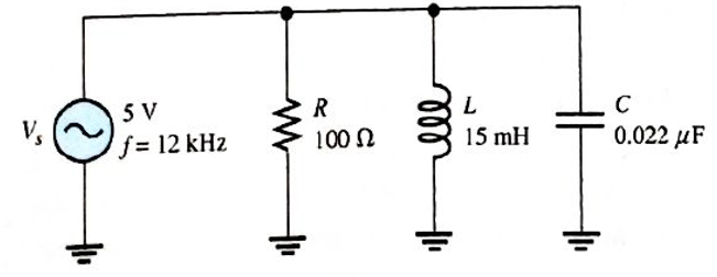
FIGURE 13-72
Expert Solution & Answer
Want to see the full answer?
Check out a sample textbook solution
Students have asked these similar questions
What is the voltage between nodes A and B in each circuit in Figure 12–73?
13. Find the output voltage when the input voltages shown in Figure 13-67 are applied to the scal-
ing adder. What is the current through R?
FIGURE 13-67
R1
Rp
10 k(2
R2
VIN=+3 Vo- W
33 k2
10 kM
R3
OVOUT
VIN3 = +3 Vo
91 k2
R4
VINA = 16 V
180 k2
A capacitor and resistor are connected in series. The resistor has a resistance of 26 ohms and the capacitor has a capacitive resistance of 16 ohms. What is the impedance of the circuit?
Chapter 13 Solutions
Electronics Fundamentals: Circuits, Devices & Applications
Ch. 13 - A series RLC circuit can have a higher voltage...Ch. 13 - The impedance of a series RLC circuit is dependent...Ch. 13 - Above the resonant frequency, series resonant...Ch. 13 - Prob. 4TFQCh. 13 - Prob. 5TFQCh. 13 - The upper and lower cutoff frequencies of a...Ch. 13 - Prob. 7TFQCh. 13 - The Q of a band-pass filter does not affect the...Ch. 13 - Prob. 9TFQCh. 13 - Prob. 10TFQ
Ch. 13 - Prob. 1STCh. 13 - The phase angle of a series RLC circuit at...Ch. 13 - The impedance at the resonant frequency of a...Ch. 13 - In a series RLC circuit that is operating below...Ch. 13 - Prob. 5STCh. 13 - Prob. 6STCh. 13 - Prob. 7STCh. 13 - Prob. 8STCh. 13 - Prob. 9STCh. 13 - Prob. 10STCh. 13 - Prob. 11STCh. 13 - Prob. 12STCh. 13 - A certain series RLC circuit operates at a...Ch. 13 - Find the impedance in Figure 13-66.Ch. 13 - If the frequency of the source voltage in Figure...Ch. 13 - For the circuit in figure 13-66, find Itot,VR,VL,...Ch. 13 - Draw the voltage phasor diagram for the circuit in...Ch. 13 - Analyze the circuit in Figure 13-67 for the...Ch. 13 - For the circuit in Figure 13-66, is the resonant...Ch. 13 - For the circuit in Figure 13-68, determine the...Ch. 13 - Find XL,XC,Z, and I at the resonant frequency in...Ch. 13 - A certain series resonant circuit has a maximum...Ch. 13 - For the RLC circuit in Figure 13-69, determine the...Ch. 13 - What is the value of the current at the half-power...Ch. 13 - Determine the resonant frequency for each filter...Ch. 13 - FIGURE 13-70 Assuming that the coils in Figure...Ch. 13 - Determine fr and BW for each filter in Figure...Ch. 13 - Find the total impedance of the circuit in Figure...Ch. 13 - Is the circuit in Figure 13-72 capacitive or...Ch. 13 - For the circuit in Figure 13-72, find all the...Ch. 13 - Find the total impedence for the circuit in Figure...Ch. 13 - What is the impedance of an ideal parallel...Ch. 13 - Prob. 21PCh. 13 - How much current is drawn from the source in...Ch. 13 - At resonance, XL=2K and RW=25 in a parallel...Ch. 13 - If the lower cutoff frequency is 2400 Hz and the...Ch. 13 - In a certain resonant circuit, the power to the...Ch. 13 - What values of L and C should be used in a tank...Ch. 13 - Prob. 27PCh. 13 - A parallel resonant band-stop filter is needed to...Ch. 13 - Prob. 29PCh. 13 - Prob. 30PCh. 13 - Prob. 31PCh. 13 - Determine whether there is a value of C that will...Ch. 13 - If the value of C is 0.22F, how much current is...Ch. 13 - Determine the resonant frequencies in Figure 13-77...Ch. 13 - Prob. 35PCh. 13 - Prob. 36PCh. 13 - Prob. 37PCh. 13 - Prob. 39PCh. 13 - Prob. 40PCh. 13 - Prob. 41PCh. 13 - Open file P13-42. Determine if there is a fault...Ch. 13 - Prob. 43P
Knowledge Booster


Learn more about
Need a deep-dive on the concept behind this application? Look no further. Learn more about this topic, electrical-engineering and related others by exploring similar questions and additional content below.Similar questions
- An R-L series circuit contains two resistors and two inductors. The resistors are 86 k and 68 k . The inductors have inductive reactances of 24 k and 56 k . The total voltage is 480 volts. Find the voltage drop across the 56-k inductor.arrow_forwardAn R-L series circuit contains two resistors and two inductors. The resistors dissipate powers of 96 watts and 125 watts. The inductors have reactive powers of 100 VARs and 78 VARs. What is the power factor?arrow_forward5. The hypotenuse has a length of 65 in., and side A has a length of 31 in. What is angle X?arrow_forward
- a capacitor and resistor are connected in series. the resistor has a resistance of 26 ohms and the capacitor has a capacitive reactance of 16 ohms. what is the impedance of the circuit?arrow_forwardGiven the following Resistances and Capacitors in Series and Voltage Source: R1 - 7 ohms R2 = 4 ohms C1 = 0.157 Farad C2 = 0.01 Farad Vs = 10,382 Volts Frequency = 86 Hz What is the Amplitude of the voltage across C1?arrow_forward1. For Figure 13-18, L = 2.25 H. Determine L FIGURE 13-18 2.25 H 3 H 7 H 3 H Lx 3 H 1 Harrow_forward
- What is the current lo in the figure if Is = 32? f Is 2A 4 A ww wwarrow_forward8. Determine the output voltage waveform in Figure 13-64. D, D2 +3 V 4.7 V 4.7 V R1 47 k2 O V qut -3 V R2 47 kN R3 10 kNarrow_forwardThe question states the angle must be within the range -90 to +90 how do I convert it to thatarrow_forward
- 4. A circuit consists of a 4 ohms resistor and a 300 μF capacitor in series. It is connected across a 60 Hz voltage source with a 500 V peak voltage. What is the phasor form of the current?arrow_forwardRefer to the circuit in given figure. The maximum time after which main SCR M get turn-off in и— sec is M + R 16 µF A 200 V L elle 64 µH 70.7 A meelarrow_forwardAn RL series circuit is connected to a 240 volt 60 hz line the capacitor has current of 1.25 amperes flowling though it. the Xc of the inductor is 22 ohms. the resistor has a resistance of 16ohms. how much voltage is dropped across the resistor?arrow_forward
arrow_back_ios
SEE MORE QUESTIONS
arrow_forward_ios
Recommended textbooks for you
 Delmar's Standard Textbook Of ElectricityElectrical EngineeringISBN:9781337900348Author:Stephen L. HermanPublisher:Cengage Learning
Delmar's Standard Textbook Of Electricity
Electrical Engineering
ISBN:9781337900348
Author:Stephen L. Herman
Publisher:Cengage Learning
Capacitors Explained - The basics how capacitors work working principle; Author: The Engineering Mindset;https://www.youtube.com/watch?v=X4EUwTwZ110;License: Standard YouTube License, CC-BY