
Electronics Fundamentals: Circuits, Devices & Applications
8th Edition
ISBN: 9780135072950
Author: Thomas L. Floyd, David Buchla
Publisher: Prentice Hall
expand_more
expand_more
format_list_bulleted
Videos
Textbook Question
Chapter 13, Problem 16P
Find the total impedance of the circuit in Figure 13-72.
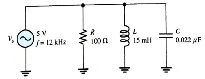
Figure 13-72
Expert Solution & Answer
Want to see the full answer?
Check out a sample textbook solution
Students have asked these similar questions
What will be magnitude of the total circuit impedance of a series LR circuit excited by a 100 Hz ac source? The resistance is 40 ohm and the inductance is 4 mF.
13. Find the output voltage when the input voltages shown in Figure 13-67 are applied to the scal-
ing adder. What is the current through R?
FIGURE 13-67
R1
Rp
10 k(2
R2
VIN=+3 Vo- W
33 k2
10 kM
R3
OVOUT
VIN3 = +3 Vo
91 k2
R4
VINA = 16 V
180 k2
8. Determine the output voltage waveform in Figure 13-64
D2
4.7 V
4.7 V
+3 V
R1
47 k
-3 V
our
R
47 k!
Ry
10 k
+
Chapter 13 Solutions
Electronics Fundamentals: Circuits, Devices & Applications
Ch. 13 - A series RLC circuit can have a higher voltage...Ch. 13 - The impedance of a series RLC circuit is dependent...Ch. 13 - Above the resonant frequency, series resonant...Ch. 13 - Prob. 4TFQCh. 13 - Prob. 5TFQCh. 13 - The upper and lower cutoff frequencies of a...Ch. 13 - Prob. 7TFQCh. 13 - The Q of a band-pass filter does not affect the...Ch. 13 - Prob. 9TFQCh. 13 - Prob. 10TFQ
Ch. 13 - Prob. 1STCh. 13 - The phase angle of a series RLC circuit at...Ch. 13 - The impedance at the resonant frequency of a...Ch. 13 - In a series RLC circuit that is operating below...Ch. 13 - Prob. 5STCh. 13 - Prob. 6STCh. 13 - Prob. 7STCh. 13 - Prob. 8STCh. 13 - Prob. 9STCh. 13 - Prob. 10STCh. 13 - Prob. 11STCh. 13 - Prob. 12STCh. 13 - A certain series RLC circuit operates at a...Ch. 13 - Find the impedance in Figure 13-66.Ch. 13 - If the frequency of the source voltage in Figure...Ch. 13 - For the circuit in figure 13-66, find Itot,VR,VL,...Ch. 13 - Draw the voltage phasor diagram for the circuit in...Ch. 13 - Analyze the circuit in Figure 13-67 for the...Ch. 13 - For the circuit in Figure 13-66, is the resonant...Ch. 13 - For the circuit in Figure 13-68, determine the...Ch. 13 - Find XL,XC,Z, and I at the resonant frequency in...Ch. 13 - A certain series resonant circuit has a maximum...Ch. 13 - For the RLC circuit in Figure 13-69, determine the...Ch. 13 - What is the value of the current at the half-power...Ch. 13 - Determine the resonant frequency for each filter...Ch. 13 - FIGURE 13-70 Assuming that the coils in Figure...Ch. 13 - Determine fr and BW for each filter in Figure...Ch. 13 - Find the total impedance of the circuit in Figure...Ch. 13 - Is the circuit in Figure 13-72 capacitive or...Ch. 13 - For the circuit in Figure 13-72, find all the...Ch. 13 - Find the total impedence for the circuit in Figure...Ch. 13 - What is the impedance of an ideal parallel...Ch. 13 - Prob. 21PCh. 13 - How much current is drawn from the source in...Ch. 13 - At resonance, XL=2K and RW=25 in a parallel...Ch. 13 - If the lower cutoff frequency is 2400 Hz and the...Ch. 13 - In a certain resonant circuit, the power to the...Ch. 13 - What values of L and C should be used in a tank...Ch. 13 - Prob. 27PCh. 13 - A parallel resonant band-stop filter is needed to...Ch. 13 - Prob. 29PCh. 13 - Prob. 30PCh. 13 - Prob. 31PCh. 13 - Determine whether there is a value of C that will...Ch. 13 - If the value of C is 0.22F, how much current is...Ch. 13 - Determine the resonant frequencies in Figure 13-77...Ch. 13 - Prob. 35PCh. 13 - Prob. 36PCh. 13 - Prob. 37PCh. 13 - Prob. 39PCh. 13 - Prob. 40PCh. 13 - Prob. 41PCh. 13 - Open file P13-42. Determine if there is a fault...Ch. 13 - Prob. 43P
Knowledge Booster


Learn more about
Need a deep-dive on the concept behind this application? Look no further. Learn more about this topic, electrical-engineering and related others by exploring similar questions and additional content below.Similar questions
- Assume the circuit shown in Figure 21-1 has an apparent power of 432 VA and a true power of 345.6 W. The capacitor has a capacitance of 15.8919 F, and the frequency is 60 Hz. Find the missing values. ET ER EC IT IR IC Z R XC VA432 P345.6W VARSC PF C15.8919Farrow_forward8. Determine the output voltage waveform in Figure 13-64. D, D2 +3 V 4.7 V 4.7 V R1 47 k2 O V qut -3 V R2 47 kN R3 10 kNarrow_forwarda capacitor and a resistor are connected in parellel to a 120 v 60 hz line the resistor has a resistance of 40 ohms and the capacitor has a capacitance of 132.6 uf what is the total current flow through the circuit. what is the impedence and the power factor and how many degrees out of phase are the current and voltage out phase with eachother.arrow_forward
- FIGURE 13-66 R +1 Vo W 22 k. 22 kQ R2 +1.8 VoW OUT 22 k) 11. Find the value of Rf necessary to produce an output that is five times the sum of the inputs in Figure 13-66.arrow_forwardDetermine the capacitance for C1 = 10 and C2 =5 connected in series and parallelarrow_forwardThis waveform, is the current in Half- .bridge With Purely capacitor Load circuit i Io T/2 T - Io True O False Oarrow_forward
- A resistor of 150 ohms, a coil with reactance 100 ohms and a capacitor with reactance 200 ohms are connected in series. What is the complex impedance R + jX?arrow_forwardA series circuit contains a 20 ohm resistor anda inductor with an inductance of 0.093H if the circuit has a fequencey of 60Hz what is the inductive reactance Xl and total impedance Z of the circuit?arrow_forwardP In RL series circuit, voltage across resistor is 6V and voltage across inductor is 8V. Power factor of the circuit isarrow_forward
- Please solve fast ,Have very less time. Do correctly . What is the total inductance in the circuit in Figure 13-1? A) 2600 uH B) 2100 mH C) 602 mH D) 800 mHarrow_forward3. An RLC series circuit has a resistor with a power consumption of 124 watts. The induc- tor has a reactive power of 366 VARST, and the capacitor has a reactive power of 288 VARSC. What is the circuit power factor?arrow_forward17 Determine the current 13. 6 -j8 6 -j8 12 100 L0° 2+ j14 Z2 O 6.324-26.57° A O 6.32426.57° A 6.32L-71.57° A O 6.32471.57° A +arrow_forward
arrow_back_ios
SEE MORE QUESTIONS
arrow_forward_ios
Recommended textbooks for you
 Delmar's Standard Textbook Of ElectricityElectrical EngineeringISBN:9781337900348Author:Stephen L. HermanPublisher:Cengage Learning
Delmar's Standard Textbook Of Electricity
Electrical Engineering
ISBN:9781337900348
Author:Stephen L. Herman
Publisher:Cengage Learning
02 - Sinusoidal AC Voltage Sources in Circuits, Part 1; Author: Math and Science;https://www.youtube.com/watch?v=8zMiIHVMfaw;License: Standard Youtube License