
Electronics Fundamentals: Circuits, Devices & Applications
8th Edition
ISBN: 9780135072950
Author: Thomas L. Floyd, David Buchla
Publisher: Prentice Hall
expand_more
expand_more
format_list_bulleted
Concept explainers
Videos
Textbook Question
Chapter 13, Problem 17P
Is the circuit in Figure 13-72 capacitive or inductive? Explain.
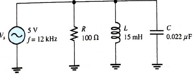
FIGURE 13-72
Expert Solution & Answer
Want to see the full answer?
Check out a sample textbook solution
Students have asked these similar questions
Please solve fast ,Have very less time.
Do correctly .
What is the total inductance in the circuit in Figure 13-1?
A) 2600 uH
B) 2100 mH
C) 602 mH
D) 800 mH
In a series LR circuit, the reactance of the inductance is 520 ohm. What will be the value of the inductor if the frequency of the AC is 60 HZ?
This waveform, is the current in Half-
.bridge With Purely capacitor Load circuit
i
Io
T/2
T
- Io
True O
False O
Chapter 13 Solutions
Electronics Fundamentals: Circuits, Devices & Applications
Ch. 13 - A series RLC circuit can have a higher voltage...Ch. 13 - The impedance of a series RLC circuit is dependent...Ch. 13 - Above the resonant frequency, series resonant...Ch. 13 - Prob. 4TFQCh. 13 - Prob. 5TFQCh. 13 - The upper and lower cutoff frequencies of a...Ch. 13 - Prob. 7TFQCh. 13 - The Q of a band-pass filter does not affect the...Ch. 13 - Prob. 9TFQCh. 13 - Prob. 10TFQ
Ch. 13 - Prob. 1STCh. 13 - The phase angle of a series RLC circuit at...Ch. 13 - The impedance at the resonant frequency of a...Ch. 13 - In a series RLC circuit that is operating below...Ch. 13 - Prob. 5STCh. 13 - Prob. 6STCh. 13 - Prob. 7STCh. 13 - Prob. 8STCh. 13 - Prob. 9STCh. 13 - Prob. 10STCh. 13 - Prob. 11STCh. 13 - Prob. 12STCh. 13 - A certain series RLC circuit operates at a...Ch. 13 - Find the impedance in Figure 13-66.Ch. 13 - If the frequency of the source voltage in Figure...Ch. 13 - For the circuit in figure 13-66, find Itot,VR,VL,...Ch. 13 - Draw the voltage phasor diagram for the circuit in...Ch. 13 - Analyze the circuit in Figure 13-67 for the...Ch. 13 - For the circuit in Figure 13-66, is the resonant...Ch. 13 - For the circuit in Figure 13-68, determine the...Ch. 13 - Find XL,XC,Z, and I at the resonant frequency in...Ch. 13 - A certain series resonant circuit has a maximum...Ch. 13 - For the RLC circuit in Figure 13-69, determine the...Ch. 13 - What is the value of the current at the half-power...Ch. 13 - Determine the resonant frequency for each filter...Ch. 13 - FIGURE 13-70 Assuming that the coils in Figure...Ch. 13 - Determine fr and BW for each filter in Figure...Ch. 13 - Find the total impedance of the circuit in Figure...Ch. 13 - Is the circuit in Figure 13-72 capacitive or...Ch. 13 - For the circuit in Figure 13-72, find all the...Ch. 13 - Find the total impedence for the circuit in Figure...Ch. 13 - What is the impedance of an ideal parallel...Ch. 13 - Prob. 21PCh. 13 - How much current is drawn from the source in...Ch. 13 - At resonance, XL=2K and RW=25 in a parallel...Ch. 13 - If the lower cutoff frequency is 2400 Hz and the...Ch. 13 - In a certain resonant circuit, the power to the...Ch. 13 - What values of L and C should be used in a tank...Ch. 13 - Prob. 27PCh. 13 - A parallel resonant band-stop filter is needed to...Ch. 13 - Prob. 29PCh. 13 - Prob. 30PCh. 13 - Prob. 31PCh. 13 - Determine whether there is a value of C that will...Ch. 13 - If the value of C is 0.22F, how much current is...Ch. 13 - Determine the resonant frequencies in Figure 13-77...Ch. 13 - Prob. 35PCh. 13 - Prob. 36PCh. 13 - Prob. 37PCh. 13 - Prob. 39PCh. 13 - Prob. 40PCh. 13 - Prob. 41PCh. 13 - Open file P13-42. Determine if there is a fault...Ch. 13 - Prob. 43P
Knowledge Booster


Learn more about
Need a deep-dive on the concept behind this application? Look no further. Learn more about this topic, electrical-engineering and related others by exploring similar questions and additional content below.Similar questions
- Assume the circuit shown in Figure 21-1 has an apparent power of 432 VA and a true power of 345.6 W. The capacitor has a capacitance of 15.8919 F, and the frequency is 60 Hz. Find the missing values. ET ER EC IT IR IC Z R XC VA432 P345.6W VARSC PF C15.8919Farrow_forwardAn R-L series circuit contains two resistors and two inductors. The resistors dissipate powers of 96 watts and 125 watts. The inductors have reactive powers of 100 VARs and 78 VARs. What is the power factor?arrow_forwardAssume the circuit in Figure 21-1 has a power factor of 68%, an apparent power of 300 VA, and a frequency of 400 Hz. The capacitor has a capacitance of 4.7125 F. Find the missing values. ET ER EC IT IR IC Z R XC VA300 P VARSC PF68 C4.7125Farrow_forward
- 8. Determine the output voltage waveform in Figure 13-64. D, D2 +3 V 4.7 V 4.7 V R1 47 k2 O V qut -3 V R2 47 kN R3 10 kNarrow_forwardDetermine the capacitance for C1 = 10 and C2 =5 connected in series and parallelarrow_forwardFor each circuit in Figure 12–70, determine the voltage across each capacitor.arrow_forward
- 8. Determine the output voltage waveform in Figure 13-64 D2 4.7 V 4.7 V +3 V R1 47 k -3 V our R 47 k! Ry 10 k +arrow_forwardWhat is the capacitor that must be added to this circuit to get a power factor of .90 The answer key: 21.879microF Can you please break down the answer in steps. Thank youarrow_forwarda capacitor and a resistor are connected in parellel to a 120 v 60 hz line the resistor has a resistance of 40 ohms and the capacitor has a capacitance of 132.6 uf what is the total current flow through the circuit. what is the impedence and the power factor and how many degrees out of phase are the current and voltage out phase with eachother.arrow_forward
- A 47-ohms load resistor is connected in series with a 10-uF capacitor. At what frequency will the capacitor reach the same value as the load resistor?arrow_forwardWhat will be magnitude of the total circuit impedance of a series LR circuit excited by a 100 Hz ac source? The resistance is 40 ohm and the inductance is 4 mF.arrow_forwardThe attached image shows a circuit with an AC voltage source, a resistor, inductor, and capacitor connected in series. The circuit has the following characteristics: Resistor resistance: 10 ohm Capacitor capacitance: 0.05 F Inductor inductance: 13 H Current Amplitude: 4 A Voltage amplitude across the source: 60 V Frequency at the source: 0.3 Hz Voltage amplitude across the resistor: 35 V Voltage amplitude across the capacitor: 37 V Voltage amplitude across the inductor: 80 V (a) Calculate the RMS voltages from the amplitudes above. From the RMS voltages across the capacitor, inductor and resistor, calculate the RMS voltage of the AC source. Hint: Vrms = V0/sqrt(2) Vrms = sqrt( (Vrms,R)2 + (Vrms, L - Vrms, C)2 ) (b) Calculate the RMS value of the current (c) Using the resistance, capacitance, inductance, and the frequency of the AC voltage, calculate the impedance Z. From this, and the previously measured value of Vrms, find the RMS value of the current in the circuit.arrow_forward
arrow_back_ios
SEE MORE QUESTIONS
arrow_forward_ios
Recommended textbooks for you
 Delmar's Standard Textbook Of ElectricityElectrical EngineeringISBN:9781337900348Author:Stephen L. HermanPublisher:Cengage Learning
Delmar's Standard Textbook Of Electricity
Electrical Engineering
ISBN:9781337900348
Author:Stephen L. Herman
Publisher:Cengage Learning
Capacitors Explained - The basics how capacitors work working principle; Author: The Engineering Mindset;https://www.youtube.com/watch?v=X4EUwTwZ110;License: Standard YouTube License, CC-BY