
Electronics Fundamentals: Circuits, Devices & Applications
8th Edition
ISBN: 9780135072950
Author: Thomas L. Floyd, David Buchla
Publisher: Prentice Hall
expand_more
expand_more
format_list_bulleted
Videos
Textbook Question
Chapter 13, Problem 11P
For the RLC circuit in Figure 13-69, determine the resonant frequency and the cutoff frequencies.
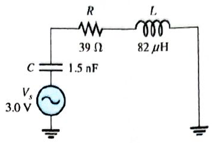
Figure 13-69
Expert Solution & Answer
Want to see the full answer?
Check out a sample textbook solution
Students have asked these similar questions
8. Determine the output voltage waveform in Figure 13-64
D2
4.7 V
4.7 V
+3 V
R1
47 k
-3 V
our
R
47 k!
Ry
10 k
+
18. A triangular waveform with a peak-to-peak voltage of 2 V and a period of I ms is applied to
the differentiator in Figure 13–70(a). What is the output voltage?
洋SV
15 k)
10 µF
10
10 kM
0.047 µF
(b)
()
Aetivate Wndew
FIGURE 13-70
What capacitance value is required for each of the varactors in the following figure to produce
a resonant frequency of 1 MHz?
VRO-
D₁
D₂
000111
2 mH
Chapter 13 Solutions
Electronics Fundamentals: Circuits, Devices & Applications
Ch. 13 - A series RLC circuit can have a higher voltage...Ch. 13 - The impedance of a series RLC circuit is dependent...Ch. 13 - Above the resonant frequency, series resonant...Ch. 13 - Prob. 4TFQCh. 13 - Prob. 5TFQCh. 13 - The upper and lower cutoff frequencies of a...Ch. 13 - Prob. 7TFQCh. 13 - The Q of a band-pass filter does not affect the...Ch. 13 - Prob. 9TFQCh. 13 - Prob. 10TFQ
Ch. 13 - Prob. 1STCh. 13 - The phase angle of a series RLC circuit at...Ch. 13 - The impedance at the resonant frequency of a...Ch. 13 - In a series RLC circuit that is operating below...Ch. 13 - Prob. 5STCh. 13 - Prob. 6STCh. 13 - Prob. 7STCh. 13 - Prob. 8STCh. 13 - Prob. 9STCh. 13 - Prob. 10STCh. 13 - Prob. 11STCh. 13 - Prob. 12STCh. 13 - A certain series RLC circuit operates at a...Ch. 13 - Find the impedance in Figure 13-66.Ch. 13 - If the frequency of the source voltage in Figure...Ch. 13 - For the circuit in figure 13-66, find Itot,VR,VL,...Ch. 13 - Draw the voltage phasor diagram for the circuit in...Ch. 13 - Analyze the circuit in Figure 13-67 for the...Ch. 13 - For the circuit in Figure 13-66, is the resonant...Ch. 13 - For the circuit in Figure 13-68, determine the...Ch. 13 - Find XL,XC,Z, and I at the resonant frequency in...Ch. 13 - A certain series resonant circuit has a maximum...Ch. 13 - For the RLC circuit in Figure 13-69, determine the...Ch. 13 - What is the value of the current at the half-power...Ch. 13 - Determine the resonant frequency for each filter...Ch. 13 - FIGURE 13-70 Assuming that the coils in Figure...Ch. 13 - Determine fr and BW for each filter in Figure...Ch. 13 - Find the total impedance of the circuit in Figure...Ch. 13 - Is the circuit in Figure 13-72 capacitive or...Ch. 13 - For the circuit in Figure 13-72, find all the...Ch. 13 - Find the total impedence for the circuit in Figure...Ch. 13 - What is the impedance of an ideal parallel...Ch. 13 - Prob. 21PCh. 13 - How much current is drawn from the source in...Ch. 13 - At resonance, XL=2K and RW=25 in a parallel...Ch. 13 - If the lower cutoff frequency is 2400 Hz and the...Ch. 13 - In a certain resonant circuit, the power to the...Ch. 13 - What values of L and C should be used in a tank...Ch. 13 - Prob. 27PCh. 13 - A parallel resonant band-stop filter is needed to...Ch. 13 - Prob. 29PCh. 13 - Prob. 30PCh. 13 - Prob. 31PCh. 13 - Determine whether there is a value of C that will...Ch. 13 - If the value of C is 0.22F, how much current is...Ch. 13 - Determine the resonant frequencies in Figure 13-77...Ch. 13 - Prob. 35PCh. 13 - Prob. 36PCh. 13 - Prob. 37PCh. 13 - Prob. 39PCh. 13 - Prob. 40PCh. 13 - Prob. 41PCh. 13 - Open file P13-42. Determine if there is a fault...Ch. 13 - Prob. 43P
Knowledge Booster


Learn more about
Need a deep-dive on the concept behind this application? Look no further. Learn more about this topic, electrical-engineering and related others by exploring similar questions and additional content below.Similar questions
- An impedance has a resistance of 60 ohms and an inductance of 0.144 henry. What series combination of R and C should be connected in parallel with the coil to make the circuit resonant at all frequencies?arrow_forwardUsually, a multistage amplifier connection can be used to increase the overall small-signal voltage gain and to provideoutput impedance. A very high B) zero (c) infinite D) very lowarrow_forwardFor each of the cascaded counter configurations in Figure below, determine the frequency of the waveform at each point indicated by a circled number, and determine the overall modulus. I kHz DIV 4 DIV 8 DIV 2 (a) DIV 10 DIV 10 DIV 10 DIV 2 100 kHz (b)arrow_forward
- 12. What is the cut off frequency in Hz for an RC series circuit if R = 1500 ohm and C = 100 nF?arrow_forwardWhat is the lower cutoff frequency due to C, C2 and C3 for circuit in figure 1? Assume re = 4.5 ohm and Beta = 200. 10ka 10 F 2N3904 10 pF 100 Ra 47 ka 1330a 47 pFarrow_forwardi e tor capacitance is increased in Figure below, the resonant frequency will increase Tuned circuit k= To exiemal componentsarrow_forward
- Exercise: Consider the series RLC circuit of Figure 1 with the source a 1-kHz sinusoid having an amplitude of 5 V. Regard the source voltage as having zero phase. Calculate the amplitude and phase (in degrees) of the following quantities: the voltage across the resistor, the voltage across the inductor, and the voltage across the capacitorarrow_forwardIn a series R-L-C circuit, the resistor has a reactance of 2 ohms, the capacitor has a capacitance of 0.5 F, and the inductance of the inductor is 9 H. What is the frequency of alternating current to achieve a resonance state?arrow_forwardCalculate the total current in the circuit below if the circuit is powered by the sine wave voltage source of 150 Vm and frequency 60 Hz. Draw the current phasor diagram and determine if this circuit fulfils the criteria of resonance. Vm Sine 60 Hz LI 0.7 H L2 0.5 H rele rele Figure Q6 C1 5.1 mF C2 -0.12 mF R1 120 Ω R2 330 Ωarrow_forward
- Describe what happens to the current in this RL series circuit as the frequency increases. Explain in general terms why the observed change should occur.arrow_forwardWhat are the uses of the resonant circuit in alternating current?arrow_forwardAn RC series circuit has a total impedance of 84 . The resistor has a value of 32 . What is the capacitive reactance of the capacitor? XC=Z2R2arrow_forward
arrow_back_ios
SEE MORE QUESTIONS
arrow_forward_ios
Recommended textbooks for you
 Delmar's Standard Textbook Of ElectricityElectrical EngineeringISBN:9781337900348Author:Stephen L. HermanPublisher:Cengage Learning
Delmar's Standard Textbook Of Electricity
Electrical Engineering
ISBN:9781337900348
Author:Stephen L. Herman
Publisher:Cengage Learning
Inductors Explained - The basics how inductors work working principle; Author: The Engineering Mindset;https://www.youtube.com/watch?v=KSylo01n5FY;License: Standard Youtube License