
Electronics Fundamentals: Circuits, Devices & Applications
8th Edition
ISBN: 9780135072950
Author: Thomas L. Floyd, David Buchla
Publisher: Prentice Hall
expand_more
expand_more
format_list_bulleted
Concept explainers
Videos
Textbook Question
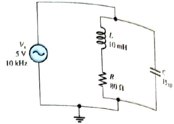
Chapter 13, Problem 19P
Find the total impedence for the circuit in Figure 13-73.
Expert Solution & Answer
Want to see the full answer?
Check out a sample textbook solution
Students have asked these similar questions
6. Determine the hysteresis voltage for each comparator in Figure 13-63. The maximum output
levels are +1 V,
R1
33 k)
150 k)
R
18 k2
68 k2
(a)
(b)
8. Determine the output voltage waveform in Figure 13-64.
D,
D2
+3 V
4.7 V
4.7 V
R1
47 k2
O V qut
-3 V
R2
47 kN
R3
10 kN
(a) An AC triangular waveform with peak values of ±2V is used as an
input to a comparator. The outputs of the comparator are
VOH=+5V, VOL=-5V
4
Draw a waveform of the output of the comparator when
an inverting circuit in Figure 5 is used.
(i)
Vi -
20
Vo
20
60
Figure 5
Chapter 13 Solutions
Electronics Fundamentals: Circuits, Devices & Applications
Ch. 13 - A series RLC circuit can have a higher voltage...Ch. 13 - The impedance of a series RLC circuit is dependent...Ch. 13 - Above the resonant frequency, series resonant...Ch. 13 - Prob. 4TFQCh. 13 - Prob. 5TFQCh. 13 - The upper and lower cutoff frequencies of a...Ch. 13 - Prob. 7TFQCh. 13 - The Q of a band-pass filter does not affect the...Ch. 13 - Prob. 9TFQCh. 13 - Prob. 10TFQ
Ch. 13 - Prob. 1STCh. 13 - The phase angle of a series RLC circuit at...Ch. 13 - The impedance at the resonant frequency of a...Ch. 13 - In a series RLC circuit that is operating below...Ch. 13 - Prob. 5STCh. 13 - Prob. 6STCh. 13 - Prob. 7STCh. 13 - Prob. 8STCh. 13 - Prob. 9STCh. 13 - Prob. 10STCh. 13 - Prob. 11STCh. 13 - Prob. 12STCh. 13 - A certain series RLC circuit operates at a...Ch. 13 - Find the impedance in Figure 13-66.Ch. 13 - If the frequency of the source voltage in Figure...Ch. 13 - For the circuit in figure 13-66, find Itot,VR,VL,...Ch. 13 - Draw the voltage phasor diagram for the circuit in...Ch. 13 - Analyze the circuit in Figure 13-67 for the...Ch. 13 - For the circuit in Figure 13-66, is the resonant...Ch. 13 - For the circuit in Figure 13-68, determine the...Ch. 13 - Find XL,XC,Z, and I at the resonant frequency in...Ch. 13 - A certain series resonant circuit has a maximum...Ch. 13 - For the RLC circuit in Figure 13-69, determine the...Ch. 13 - What is the value of the current at the half-power...Ch. 13 - Determine the resonant frequency for each filter...Ch. 13 - FIGURE 13-70 Assuming that the coils in Figure...Ch. 13 - Determine fr and BW for each filter in Figure...Ch. 13 - Find the total impedance of the circuit in Figure...Ch. 13 - Is the circuit in Figure 13-72 capacitive or...Ch. 13 - For the circuit in Figure 13-72, find all the...Ch. 13 - Find the total impedence for the circuit in Figure...Ch. 13 - What is the impedance of an ideal parallel...Ch. 13 - Prob. 21PCh. 13 - How much current is drawn from the source in...Ch. 13 - At resonance, XL=2K and RW=25 in a parallel...Ch. 13 - If the lower cutoff frequency is 2400 Hz and the...Ch. 13 - In a certain resonant circuit, the power to the...Ch. 13 - What values of L and C should be used in a tank...Ch. 13 - Prob. 27PCh. 13 - A parallel resonant band-stop filter is needed to...Ch. 13 - Prob. 29PCh. 13 - Prob. 30PCh. 13 - Prob. 31PCh. 13 - Determine whether there is a value of C that will...Ch. 13 - If the value of C is 0.22F, how much current is...Ch. 13 - Determine the resonant frequencies in Figure 13-77...Ch. 13 - Prob. 35PCh. 13 - Prob. 36PCh. 13 - Prob. 37PCh. 13 - Prob. 39PCh. 13 - Prob. 40PCh. 13 - Prob. 41PCh. 13 - Open file P13-42. Determine if there is a fault...Ch. 13 - Prob. 43P
Knowledge Booster


Learn more about
Need a deep-dive on the concept behind this application? Look no further. Learn more about this topic, electrical-engineering and related others by exploring similar questions and additional content below.Similar questions
- 8. Determine the output voltage waveform in Figure 13-64 D2 4.7 V 4.7 V +3 V R1 47 k -3 V our R 47 k! Ry 10 k +arrow_forwardthe following waveform is the inductor current of the buck converter, the ripple current is equal to Q7) the following waveform is the inductor current of the buck converter, the ripple current is equal to Inductor current 35 30- 25- 20- Lead voltage Oa) 14A b) 15A c) 16A d) 17Aarrow_forwardQ/ Why is high frequency (Fsw ) used in Buck Converter circuitsarrow_forward
- Usually, a multistage amplifier connection can be used to increase the overall small-signal voltage gain and to provideoutput impedance. A very high B) zero (c) infinite D) very lowarrow_forwardWhen in forward biased, what have you noticed when you change the source voltage from 0V to +20V? When in reverse biased, what have you noticed when changing the source voltage from 0 V to -15V?arrow_forward21. The sequences of voltage levels shown in Figure 13-72 are applied to the summing amplifier and the indicated output is observed. First, determine if this output is correct. If it is not correct, determine the fault. +3 V +2 V +1.5 V V +1 V +2 V +1.5 V +I V R VIN O V R1 -I V +1,5 V W- VINI OWW VINA O V OV R2 -0.5 V YNOW OVOUT -3 V +3 V R3 YINI OW VOUT All resistors are 10 k. -IV -IV -2 V -4.5 V A FIGURE 13-72arrow_forward
- What is the minimum detectable temperature change that the A-to-D converter can resolve?arrow_forwardIn the figure if the trigger angle of thyristors is a = 60 The waveform of the load current drawarrow_forwardwhat is the output voltage of this circuit if Vx=3.9Vpp & Vy=5.5Vpp sinewave at 1 KHz?arrow_forward
arrow_back_ios
SEE MORE QUESTIONS
arrow_forward_ios
Recommended textbooks for you
 Delmar's Standard Textbook Of ElectricityElectrical EngineeringISBN:9781337900348Author:Stephen L. HermanPublisher:Cengage Learning
Delmar's Standard Textbook Of Electricity
Electrical Engineering
ISBN:9781337900348
Author:Stephen L. Herman
Publisher:Cengage Learning
Capacitors Explained - The basics how capacitors work working principle; Author: The Engineering Mindset;https://www.youtube.com/watch?v=X4EUwTwZ110;License: Standard YouTube License, CC-BY