
Concept explainers
Videos
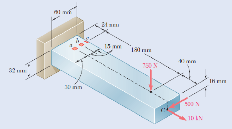
Three forces are applied to the bar shown. Determine the normal and shearing stresses at (a) point a, (b) point b, (c) point c.
Fig. P8.47
(a)
The normal and shearing stress at point a.
Answer to Problem 47P
The normal stress at point a is
The shear stress at point a is
Explanation of Solution
Given information:
The centric force p is
Calculation:
At point A:
Find the area of cross section
Here, b is the width of the bar and h is the height of the bar.
Substitute
Find the moment of inertia
Substitute
Find the moment of inertia
Substitute
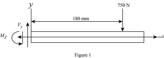
Sketch the side view of bar as shown in Figure 1.
At the section containing point a, b, and c.
Refer to Figure 1.
Find the moment about z axis as follows:
Sketch the side view of bar as shown in Figure 2.
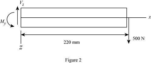
Find the moment about y axis as follows:
Find the normal stress
Here, P is the centric force, A is the area of rectangular cross section,
Substitute
Thus, the normal stress at point a is
Sketch the cross section at point a as shown in figure 3.
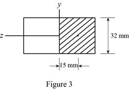
Determine the first moment area (Q) as follows:
Here,
Refer to Figure 2.
Substitute
Find the shear stress
Here,
Substitute
Thus, the shear stress at point a is
(b)
The normal and shearing stresses at point b.
Answer to Problem 47P
The normal stress at point b is
The shear stress at point b is
Explanation of Solution
Calculation:
At point b:
Find the normal stress
Substitute
Thus, the normal stress at point b is
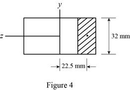
Sketch the cross section at point b as shown in figure 4.
Determine the first moment area (Q) as follows:
Here,
Refer to Figure 2.
Substitute
Find the shear stress
Here,
Substitute
Thus, the shear stress at point b is
(c)
The normal and shearing stresses at point c.
Answer to Problem 47P
The normal stress at point c is
The shear stress at point c is
Explanation of Solution
Calculation:
Find the normal stress
Substitute
Thus, the normal stress at point c is
Find the shear stress
The point c is edge on the cross section. Since Q is zero.
Substitute
Thus, the shear stress at point c is
Want to see more full solutions like this?
Chapter 8 Solutions
Mechanics of Materials, 7th Edition


- 2/Y Y+1 2Cp Q1/ Show that Cda Az x P1 mactual Cdf Af R/T₁ 2pf(P1-P2-zxgxpf) Q2/ A simple jet carburetor has to supply 5 Kg of air per minute. The air is at a pressure of 1.013 bar and a temperature of 27 °C. Calculate the throat diameter of the choke for air flow velocity of 90 m/sec. Take velocity coefficient to be 0.8. Assume isentropic flow and the flow to be compressible. Quiz/ Determine the air-fuel ratio supplied at 5000 m altitude by a carburetor which is adjusted to give an air-fuel ratio of 14:1 at sea level where air temperature is 27 °C and pressure is 1.013 bar. The temperature of air decreases with altitude as given by the expression The air pressure decreases with altitude as per relation h = 19200 log10 (1.013), where P is in bar. State any assumptions made. t = ts P 0.0065harrow_forward36 2) Use the method of MEMBERS to determine the true magnitude and direction of the forces in members1 and 2 of the frame shown below in Fig 3.2. 300lbs/ft member-1 member-2 30° Fig 3.2. https://brightspace.cuny.edu/d21/le/content/433117/viewContent/29873977/Viewarrow_forwardCan you solve this for me?arrow_forward
- 5670 mm The apartment in the ground floor of three floors building in Fig. in Baghdad city. The details of walls, roof, windows and door are shown. The window is a double glazing and air space thickness is 1.3cm Poorly Fitted-with Storm Sash with wood strip and storm window of 0.6 cm glass thickness. The thickness of door is 2.5 cm. The door is Poor Installation. There are two peoples in each room. The height of room is 280 cm. assume the indoor design conditions are 25°C DBT and 50 RH, and moisture content of 8 gw/kga. The moisture content of outdoor is 10.5 gw/kga. Calculate heat gain for living room : الشقة في الطابق الأرضي من مبنى ثلاثة طوابق في مدينة بغداد يظهر في مخطط الشقة تفاصيل الجدران والسقف والنوافذ والباب. النافذة عبارة عن زجاج مزدوج وسمك الفراغ الهوائي 1.3 سم ضعيف الاحكام مع ساتر حماية مع إطار خشبي والنافذة بسماكة زجاج 0.6 سم سماكة الباب 2.5 سم. الباب هو تركيب ضعيف هناك شخصان في كل غرفة. ارتفاع الغرفة 280 سم. افترض أن ظروف التصميم الداخلي هي DBT25 و R50 ، ومحتوى الرطوبة 8…arrow_forwardHow do i solve this problem?arrow_forwardQ4/ A compressor is driven motor by mean of a flat belt of thickness 10 mm and a width of 250 mm. The motor pulley is 300 mm diameter and run at 900 rpm and the compressor pulley is 1500 mm diameter. The shaft center distance is 1.5 m. The angle of contact of the smaller pulley is 220° and on the larger pulley is 270°. The coefficient of friction between the belt and the small pulley is 0.3, and between the belt and the large pulley is 0.25. The maximum allowable belt stress is 2 MPa and the belt density is 970 kg/m³. (a) What is the power capacity of the drive and (b) If the small pulley replaced by V-grooved pulley of diameter 300 mm, grooved angle of 34° and the coefficient of friction between belt and grooved pulley is 0.35. What will be the power capacity in this case, assuming that the diameter of the large pulley remain the same of 1500 mm.arrow_forward
- You are tasked with designing a power drive system to transmit power between a motor and a conveyor belt in a manufacturing facility as illustrated in figure. The design must ensure efficient power transmission, reliability, and safety. Given the following specifications and constraints, design drive system for this application: Specifications: Motor Power: The electric motor provides 10 kW of power at 1,500 RPM. Output Speed: The output shaft should rotate at 150 rpm. Design Decisions: Transmission ratio: Determine the necessary drive ratio for the system. Shaft Diameter: Design the shafts for both the motor and the conveyor end. Material Selection: Choose appropriate materials for the gears, shafts. Bearings: Select suitable rolling element bearings. Constraints: Space Limitation: The available space for the gear drive system is limited to a 1-meter-long section. Attribute 4 of CEP Depth of knowledge required Fundamentals-based, first principles analytical approach…arrow_forward- | العنوان In non-continuous dieless drawing process for copper tube as shown in Fig. (1), take the following data: Do-20mm, to=3mm, D=12mm, ti/to=0.6 and v.-15mm/s. Calculate: (1) area reduction RA, (2) drawing velocity v. Knowing that: ti: final thickness V. Fig. (1) ofthrearrow_forwardA direct extrusion operation produces the cross section shown in Fig. (2) from an aluminum billet whose diameter 160 mm and length - 700 mm. Determine the length of the extruded section at the end of the operation if the die angle -14° 60 X Fig. (2) Note: all dimensions in mm.arrow_forward
- For hot rolling processes, show that the average strain rate can be given as: = (1+5)√RdIn(+1)arrow_forward: +0 usão العنوان on to A vertical true centrifugal casting process is used to produce bushings that are 250 mm long and 200 mm in outside diameter. If the rotational speed during solidification is 500 rev/min, determine the inside radii at the top and bottom of the bushing if R-2R. Take: -9.81 mis ۲/۱ ostrararrow_forward: +0 العنوان use only In conventional drawing of a stainless steel wire, the original diameter D.-3mm, the area reduction at each die stand r-40%, and the proposed final diameter D.-0.5mm, how many die stands are required to complete this process. онarrow_forward
 Elements Of ElectromagneticsMechanical EngineeringISBN:9780190698614Author:Sadiku, Matthew N. O.Publisher:Oxford University Press
 Mechanics of Materials (10th Edition)Mechanical EngineeringISBN:9780134319650Author:Russell C. HibbelerPublisher:PEARSON
 Thermodynamics: An Engineering ApproachMechanical EngineeringISBN:9781259822674Author:Yunus A. Cengel Dr., Michael A. BolesPublisher:McGraw-Hill Education
 Control Systems EngineeringMechanical EngineeringISBN:9781118170519Author:Norman S. NisePublisher:WILEY
 Mechanics of Materials (MindTap Course List)Mechanical EngineeringISBN:9781337093347Author:Barry J. Goodno, James M. GerePublisher:Cengage Learning
 Engineering Mechanics: StaticsMechanical EngineeringISBN:9781118807330Author:James L. Meriam, L. G. Kraige, J. N. BoltonPublisher:WILEY