
Mechanics of Materials, 7th Edition
7th Edition
ISBN: 9780073398235
Author: Ferdinand P. Beer, E. Russell Johnston Jr., John T. DeWolf, David F. Mazurek
Publisher: McGraw-Hill Education
expand_more
expand_more
format_list_bulleted
Concept explainers
Videos
Textbook Question
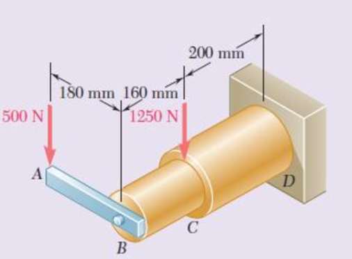
Chapter 8, Problem 66RP
Neglecting the effect of fillets and of stress concentrations, determine the smallest permissible diameters of the solid rods BC and CD. Use τall = 60 MPa.
Fig. P8.66 and P8.67
Expert Solution & Answer
Want to see the full answer?
Check out a sample textbook solution
Students have asked these similar questions
A spherical gas tank is fabricated by bolting together two thin-walled
hemispherical shells with an inner diameter of 8 m. The gas is
pressurized to 2.0 MPa. The shells have an allowable normal stress
of 150 MPa, and the 25 mm-diameter bolts have an allowable normal
stress of 250 MPa.
(a) Determine the minimum thickness of the walls of the tank to the
nearest mm.
(b) Determine the minimum number of bolts to connect the hemispheres.
A 20 mm diameter steel rod passes
concentrically through a bronze tube
(200+SN) mm long, 50 mm external
diameter and 40 mm internal diameter. The
ends of the steel rod are threaded and
provided with nuts and washers which are
adjusted initially so that there is no end play
at 25°C.. 1. Assuming that there is no change
in the thickness of the washers, if the stress
produced in the steel is (200+SN) MN/m2
when one of the nuts is tightened, the pitch
of the thread being 1 mm. Find the number
of turns for the nut and stress in bronze
tube.2. If the temperature of the steel and
bronze is then raised to 4O°C find the
changes that will occur in the stresses in
both materials. The coefficient of linear
expansion per C is 10 x10-6 for steel and 17
x10-6 for bronze. E for steel = 210 GN/m2. E
%3D
for bronze = 100 GN/m2.. Note: SN =
%3D
Student number
Student Number
=32
A lightweight lever consists of a 0.8m solid bar rigidly mounted to a large structure and a 0.5m solid lever
welded to the solid bar. Using the loading indicated and assuming the material has a Young's Modulus of
200 GPa and a shear modulus of 86 GPa, calculate:
(a) the maximum stress at Point A on the Cross-section a-a,
(b) the vertical displacement of the knob when the load is applied relative to Cross-section a-a.
B
C
50 mm
Section ad
a 0.8 m
0.5 m
100 N
38 mm
Focus
Chapter 8 Solutions
Mechanics of Materials, 7th Edition
Ch. 8.2 - A W10 = 39 rolled-steel beam supports a load P as...Ch. 8.2 - Solve Prob. 8.1, assuming that P = 22.5 kips and a...Ch. 8.2 - An overhanging W920 449 rolled-steel beam...Ch. 8.2 - Solve Prob. 8.3, assuming that P = 850 kN and a =...Ch. 8.2 - 8.5 and 8.6 (a) Knowing that all = 160 MPa and all...Ch. 8.2 - 8.5 and 8.6 (a) Knowing that all = 160 MPa and all...Ch. 8.2 - 8.7 and 8.8 (a) Knowing that all = 24 ksi and all...Ch. 8.2 - 8.7 and 8.8 (a) Knowing that all = 24 ksi and all...Ch. 8.2 - 8.9 through 8.14 Each of the following problems...Ch. 8.2 - 8.9 through 8.14 Each of the following problems...
Ch. 8.2 - 8.9 through 8.14 Each of the following problems...Ch. 8.2 - Prob. 12PCh. 8.2 - 8.9 through 8.14 Each of the following problems...Ch. 8.2 - 8.9 through 8.14 Each of the following problems...Ch. 8.2 - Determine the smallest allowable diameter of the...Ch. 8.2 - Determine the smallest allowable diameter of the...Ch. 8.2 - Using the notation of Sec. 8.2 and neglecting the...Ch. 8.2 - The 4-kN force is parallel to the x axis, and the...Ch. 8.2 - The vertical force P1 and the horizontal force P2...Ch. 8.2 - The two 500-lb forces are vertical and the force P...Ch. 8.2 - Prob. 21PCh. 8.2 - Prob. 22PCh. 8.2 - The solid shaft AB rotates at 600 rpm and...Ch. 8.2 - The solid shaft AB rotates at 600 rpm and...Ch. 8.2 - The solid shafts ABC and DEF and the gears shown...Ch. 8.2 - Prob. 26PCh. 8.2 - Prob. 27PCh. 8.2 - Prob. 28PCh. 8.2 - The solid shaft AE rotates at 600 rpm and...Ch. 8.2 - The solid shaft AE rotates at 600 rpm and...Ch. 8.3 - Two 1.2-kip forces are applied to an L-shaped...Ch. 8.3 - Two 1.2-kip forces are applied to an L-shaped...Ch. 8.3 - The cantilever beam AB has a rectangular cross...Ch. 8.3 - 8.34 through 8.36 Member AB has a uniform...Ch. 8.3 - 8.34 through 8.36 Member AB has a uniform...Ch. 8.3 - 8.34 through 8.36 Member AB has a uniform...Ch. 8.3 - Prob. 37PCh. 8.3 - Two forces are applied to the pipe AB as shown....Ch. 8.3 - Several forces are applied to the pipe assembly...Ch. 8.3 - The steel pile AB has a 100-mm outer diameter and...Ch. 8.3 - Three forces are applied to a 4-in.-diameter plate...Ch. 8.3 - The steel pipe AB has a 72-mm outer diameter and a...Ch. 8.3 - A 13-kN force is applied as shown to the...Ch. 8.3 - A vertical force P of magnitude 60 lb is applied...Ch. 8.3 - Three forces are applied to the bar shown....Ch. 8.3 - Prob. 46PCh. 8.3 - Three forces are applied to the bar shown....Ch. 8.3 - Three forces are applied to the bar shown....Ch. 8.3 - Two forces are applied to the small post BD as...Ch. 8.3 - Two forces are applied to the small post BD as...Ch. 8.3 - Three forces are applied to the machine component...Ch. 8.3 - Prob. 52PCh. 8.3 - Three steel plates, each 13 mm thick, are welded...Ch. 8.3 - Three steel plates, each 13 mm thick, are welded...Ch. 8.3 - Two forces P1 and P2 are applied as shown in...Ch. 8.3 - Two forces P1 and P2 are applied as shown in...Ch. 8.3 - Prob. 57PCh. 8.3 - Four forces are applied to a W8 28 rolled-steel...Ch. 8.3 - A force P is applied to a cantilever beam by means...Ch. 8.3 - Prob. 60PCh. 8.3 - A 5-kN force P is applied to a wire that is...Ch. 8.3 - Knowing that the structural tube shown has a...Ch. 8.3 - The structural tube shown has a uniform wall...Ch. 8.3 - The structural tube shown has a uniform wall...Ch. 8 - (a) Knowing that all = 24 ksi and all = 14.5 ksi,...Ch. 8 - Neglecting the effect of fillets and of stress...Ch. 8 - Knowing that rods BC and CD are of diameter 24 mm...Ch. 8 - The solid shaft AB rotates at 450 rpm and...Ch. 8 - A 6-kip force is applied to the machine element AB...Ch. 8 - A thin strap is wrapped around a solid rod of...Ch. 8 - A close-coiled spring is made of a circular wire...Ch. 8 - Forces are applied at points A and B of the solid...Ch. 8 - Knowing that the bracket AB has a uniform...Ch. 8 - For the post and loading shown, determine the...Ch. 8 - Knowing that the structural tube shown has a...Ch. 8 - The cantilever beam AB will be installed so that...
Knowledge Booster


Learn more about
Need a deep-dive on the concept behind this application? Look no further. Learn more about this topic, mechanical-engineering and related others by exploring similar questions and additional content below.Similar questions
- Problem No. 2 A cylindrical boiler with an outside diameter of 2.75 m and a wall thickness of 32 mm is made of a steel alloy that has a yield stress of 340 MPa. Determine: (a) the maximum normal stress produced by an internal pressure of 2.3 MPa.(b) the maximum allowable pressure if a factor of safety of 4.5 with respect to yield is requiredarrow_forward6. Link BD consists of a single bar 30 mm wide and 12 mm thick. Knowing that each pin has a 10 mm diameter, determine the maximum value of the average normal stress in link BD if (a) 0 = 0°, (b) 0 = 90°. 150 m 00 mm 5B Page 2 of 3arrow_forwardProblem 1: Two solid cylindrical rods AB and BC are welded together at B and loaded as shown below. Knowing that P = 8 kips, find the average normal stress at the midsection of (a) rod AB, and (b) rod BC. Begin your solution on this page. 30 in. 25 in. B C P - 1.25 in. 12 kips 0.75 in.arrow_forward
- A timber column, 8 in. by 8 in. in cross section, is reinforced on all four sides by steel plates, each plate being 8 in. wide and t in. thick. Determine the smallest value of tfor which the column can support an axial load of 300 kips if the working stresses are 1200 psi for timber and 20 ksi for steel. The moduli of elasticity are 1.5 x10⁶psi for timber and 29 x 106psi for steel.arrow_forwardQ # 2 The state of plane stress shown is expected to 6 |13 MPа occur in an aluminum casting. Knowing that for the aluminum alloy used oUT =100 MPa and Ouc = 250 MPa and using Mohr's criterion, determine whether rupture of the casting will occur or not. 21 MPa 46 MPaarrow_forwardTwo solid cylindrical rods (1) and (2) are joined together at flange B and loaded, as shown. If the normal stress in each rod must be limited to 107 MPa, determine the minimum diameter required for rod 1 and rod 2. Assume P = 80 kN and Q = 140 kN. Express your answer in mm rounded to the nearest hundredths.arrow_forward
- A draw bar between a tractor and a trailer is made from a length of steel with a rectangular cross-section 100 mm by 12 mm. The load is transmitted to the bar via a pin through a 25 mm diameter hole at each end as shown in Fig. 4c. for 100 Fig. 4c If the load P in the bar is 100 kN, determine the following: The stress at the section X-X, shown in Fig. 4c. i (6 marks) ii The stress at the section Y-Y, shown in Fig. 4c. (5 marks)arrow_forwardTwo links BF are made of steel with a 450-MPa ultimate normal stress and has a 6x12–mm uniform rectangular cross section. Links BF are connected to members ABD and CDEF by 8-mm diameter pins; ABD and CDEF are connected together by a 10-mm diameter pin; CDEF is connected to the support by a 10-mm diameter pin; all of the pins are made of steel with a 170 MPa ultimate shearing stress. Knowing that a factor of safety of 3 is desired, determine the largest load P that may be appliedarrow_forward3 Required information Two horizontal 9.5-kip forces (P) are applied to pin B of the assembly shown. A 0.8-in. diameter pin is used at each connection. Part 1 of 2 0.5 in. 1.8 in. 0.5 in. 60° 45°% -1.8 in. Determine the maximum value of the average normal stress in link AB. The maximum value of the average normal stress in link AB is ksi.arrow_forward
- Two solid cylindrical rods (1) and (2) are joined together at flange B and loaded, as shown. If the normal stress in each rod must be limited to 107 MPa, determine the minimum diameter required for rod 1. Assume P = 80 kN and Q = 140 kN. Express your answer in mm rounded to the nearest hundredths.arrow_forwardQuestion- 1) Two gage marks are placed exactly 270 mm apart on a 10-mm-diameter aluminum rod with E = 72 GPa and an ultimate strength of 150 MPa. It is Know that the distance between the gage marks is 270.28 mm after a load is applied, determine the stress in the rodarrow_forwardQuestion 1 Not yet answered Marked out of 2.00 P Flag question the bar shown is subjected to uniform tensile stresses along the x and y axes of a magnitude 676 MPa. if the length a = 45 mm and the length b = 34 mm if the modulus of elasticity E = 120 GP, and the Poisson's ratio is 0.3 then, its new length b is mm a a. 34.1915 b. 34.0575 C. 168.0733 d. 34.1341arrow_forward
arrow_back_ios
SEE MORE QUESTIONS
arrow_forward_ios
Recommended textbooks for you
 Elements Of ElectromagneticsMechanical EngineeringISBN:9780190698614Author:Sadiku, Matthew N. O.Publisher:Oxford University Press
 Mechanics of Materials (10th Edition)Mechanical EngineeringISBN:9780134319650Author:Russell C. HibbelerPublisher:PEARSON
 Thermodynamics: An Engineering ApproachMechanical EngineeringISBN:9781259822674Author:Yunus A. Cengel Dr., Michael A. BolesPublisher:McGraw-Hill Education
 Control Systems EngineeringMechanical EngineeringISBN:9781118170519Author:Norman S. NisePublisher:WILEY
 Mechanics of Materials (MindTap Course List)Mechanical EngineeringISBN:9781337093347Author:Barry J. Goodno, James M. GerePublisher:Cengage Learning
 Engineering Mechanics: StaticsMechanical EngineeringISBN:9781118807330Author:James L. Meriam, L. G. Kraige, J. N. BoltonPublisher:WILEY
Elements Of Electromagnetics
Mechanical Engineering
ISBN:9780190698614
Author:Sadiku, Matthew N. O.
Publisher:Oxford University Press
Mechanics of Materials (10th Edition)
Mechanical Engineering
ISBN:9780134319650
Author:Russell C. Hibbeler
Publisher:PEARSON
Thermodynamics: An Engineering Approach
Mechanical Engineering
ISBN:9781259822674
Author:Yunus A. Cengel Dr., Michael A. Boles
Publisher:McGraw-Hill Education
Control Systems Engineering
Mechanical Engineering
ISBN:9781118170519
Author:Norman S. Nise
Publisher:WILEY
Mechanics of Materials (MindTap Course List)
Mechanical Engineering
ISBN:9781337093347
Author:Barry J. Goodno, James M. Gere
Publisher:Cengage Learning
Engineering Mechanics: Statics
Mechanical Engineering
ISBN:9781118807330
Author:James L. Meriam, L. G. Kraige, J. N. Bolton
Publisher:WILEY
EVERYTHING on Axial Loading Normal Stress in 10 MINUTES - Mechanics of Materials; Author: Less Boring Lectures;https://www.youtube.com/watch?v=jQ-fNqZWrNg;License: Standard YouTube License, CC-BY