
Mechanics of Materials, 7th Edition
7th Edition
ISBN: 9780073398235
Author: Ferdinand P. Beer, E. Russell Johnston Jr., John T. DeWolf, David F. Mazurek
Publisher: McGraw-Hill Education
expand_more
expand_more
format_list_bulleted
Concept explainers
Videos
Textbook Question
Chapter 8.3, Problem 43P
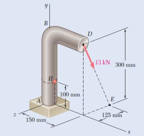
A 13-kN force is applied as shown to the 60-mm-diameter cast-iron post ABD. At point H, determine (a) the principal stresses and principal planes, (b) the maximum shearing stress.
Fig. P8.43
Expert Solution & Answer
Want to see the full answer?
Check out a sample textbook solution
Students have asked these similar questions
1.4 kN - m
PROBLEM 8.43
A 10-kN force and a 1.4-kN - m couple are applied at the top of the 65-mm
diameter brass post shown. Determine the principal stresses and maximum
shearing stress at (a) point H, (b) point K.
10 kN
240 mm
Omax = 30.0 MPa
O min =-30.0 MPa
Tmax = 30.0 MPa
Omax = 7.02 MPa
Omin =-96.0 MPa
Tmay =51.5 MPa
Problem 4
The steel pipe AB has a 102-mam outer diameter and a 6-mm wall thickness.
Knowing that arm CD is rigidly attached to the pipe, determine the principal stresses
and the maximum shearing stress at point K. And then show stress on Mohr's circle.
200 mm
6 mm
B
H
D
51 mm
150 mm
x
A steel pipe of 300-mm outer diameter is fabricated from an 8-mm-thick plate by welding along a helix that forms an angle of 20° with
a plane perpendicular to the axis of the pipe. Knowing that a 250-kN axial force P and a 12-kN-m torque T. each directed as shown, are
applied to the pipe, determine the normal and in-plane shearing stresses in directions, respectively, normal and tangential to the weld.
T
The normal stress is -
The shear stress is-
Weld
20⁰
8 mm
MPa
MPa.
Chapter 8 Solutions
Mechanics of Materials, 7th Edition
Ch. 8.2 - A W10 = 39 rolled-steel beam supports a load P as...Ch. 8.2 - Solve Prob. 8.1, assuming that P = 22.5 kips and a...Ch. 8.2 - An overhanging W920 449 rolled-steel beam...Ch. 8.2 - Solve Prob. 8.3, assuming that P = 850 kN and a =...Ch. 8.2 - 8.5 and 8.6 (a) Knowing that all = 160 MPa and all...Ch. 8.2 - 8.5 and 8.6 (a) Knowing that all = 160 MPa and all...Ch. 8.2 - 8.7 and 8.8 (a) Knowing that all = 24 ksi and all...Ch. 8.2 - 8.7 and 8.8 (a) Knowing that all = 24 ksi and all...Ch. 8.2 - 8.9 through 8.14 Each of the following problems...Ch. 8.2 - 8.9 through 8.14 Each of the following problems...
Ch. 8.2 - 8.9 through 8.14 Each of the following problems...Ch. 8.2 - Prob. 12PCh. 8.2 - 8.9 through 8.14 Each of the following problems...Ch. 8.2 - 8.9 through 8.14 Each of the following problems...Ch. 8.2 - Determine the smallest allowable diameter of the...Ch. 8.2 - Determine the smallest allowable diameter of the...Ch. 8.2 - Using the notation of Sec. 8.2 and neglecting the...Ch. 8.2 - The 4-kN force is parallel to the x axis, and the...Ch. 8.2 - The vertical force P1 and the horizontal force P2...Ch. 8.2 - The two 500-lb forces are vertical and the force P...Ch. 8.2 - Prob. 21PCh. 8.2 - Prob. 22PCh. 8.2 - The solid shaft AB rotates at 600 rpm and...Ch. 8.2 - The solid shaft AB rotates at 600 rpm and...Ch. 8.2 - The solid shafts ABC and DEF and the gears shown...Ch. 8.2 - Prob. 26PCh. 8.2 - Prob. 27PCh. 8.2 - Prob. 28PCh. 8.2 - The solid shaft AE rotates at 600 rpm and...Ch. 8.2 - The solid shaft AE rotates at 600 rpm and...Ch. 8.3 - Two 1.2-kip forces are applied to an L-shaped...Ch. 8.3 - Two 1.2-kip forces are applied to an L-shaped...Ch. 8.3 - The cantilever beam AB has a rectangular cross...Ch. 8.3 - 8.34 through 8.36 Member AB has a uniform...Ch. 8.3 - 8.34 through 8.36 Member AB has a uniform...Ch. 8.3 - 8.34 through 8.36 Member AB has a uniform...Ch. 8.3 - Prob. 37PCh. 8.3 - Two forces are applied to the pipe AB as shown....Ch. 8.3 - Several forces are applied to the pipe assembly...Ch. 8.3 - The steel pile AB has a 100-mm outer diameter and...Ch. 8.3 - Three forces are applied to a 4-in.-diameter plate...Ch. 8.3 - The steel pipe AB has a 72-mm outer diameter and a...Ch. 8.3 - A 13-kN force is applied as shown to the...Ch. 8.3 - A vertical force P of magnitude 60 lb is applied...Ch. 8.3 - Three forces are applied to the bar shown....Ch. 8.3 - Prob. 46PCh. 8.3 - Three forces are applied to the bar shown....Ch. 8.3 - Three forces are applied to the bar shown....Ch. 8.3 - Two forces are applied to the small post BD as...Ch. 8.3 - Two forces are applied to the small post BD as...Ch. 8.3 - Three forces are applied to the machine component...Ch. 8.3 - Prob. 52PCh. 8.3 - Three steel plates, each 13 mm thick, are welded...Ch. 8.3 - Three steel plates, each 13 mm thick, are welded...Ch. 8.3 - Two forces P1 and P2 are applied as shown in...Ch. 8.3 - Two forces P1 and P2 are applied as shown in...Ch. 8.3 - Prob. 57PCh. 8.3 - Four forces are applied to a W8 28 rolled-steel...Ch. 8.3 - A force P is applied to a cantilever beam by means...Ch. 8.3 - Prob. 60PCh. 8.3 - A 5-kN force P is applied to a wire that is...Ch. 8.3 - Knowing that the structural tube shown has a...Ch. 8.3 - The structural tube shown has a uniform wall...Ch. 8.3 - The structural tube shown has a uniform wall...Ch. 8 - (a) Knowing that all = 24 ksi and all = 14.5 ksi,...Ch. 8 - Neglecting the effect of fillets and of stress...Ch. 8 - Knowing that rods BC and CD are of diameter 24 mm...Ch. 8 - The solid shaft AB rotates at 450 rpm and...Ch. 8 - A 6-kip force is applied to the machine element AB...Ch. 8 - A thin strap is wrapped around a solid rod of...Ch. 8 - A close-coiled spring is made of a circular wire...Ch. 8 - Forces are applied at points A and B of the solid...Ch. 8 - Knowing that the bracket AB has a uniform...Ch. 8 - For the post and loading shown, determine the...Ch. 8 - Knowing that the structural tube shown has a...Ch. 8 - The cantilever beam AB will be installed so that...
Knowledge Booster


Learn more about
Need a deep-dive on the concept behind this application? Look no further. Learn more about this topic, mechanical-engineering and related others by exploring similar questions and additional content below.Similar questions
- 7. Knowing that 0=40° and P=9 kN, determine (a) the smallest allowable diameter of the pin at Bif the average shearing stress in the pin is not exceed 120 MPa, (b) the corresponding average bearing stress in the member AB at B, (c) the corresponding average bearing stress in each of the support brackets at B. P 16 mm 750 mm 750 mm 50 mm- 12 inmarrow_forward19. knowing that a force P of magnitude 75 N is applied to the pedestal shown, determine (a) the diameter of the pin at C for which the average shearing stress in the pin is 40 MPa, (b) the corresponding bearing stress in the pedestal at C, (c) the corresponding bearing stress in each support bracket at C. 75 mm 9 mm - 300 mm- B 125 mm D 5 mmarrow_forwardProblem 2. Three loads are applied to the short rectangular post shown In Fig. 2(a). The cross- sectional dimensions of the post are shown in Fig. 2(b). Determine: Me (a) The normal and shear stresses and points H and K; (b) The principal stresses and maximum in-plane shear stress at point H, and show the orientation of theses stresses in an appropriate sketch. No. M2 y 50 mm 210 kN %3D 120 mm (Naー 75 mm K 65 kN 30 mm 95 kN 160 mm 150 mm 30 mm Y-axis is the w to the sectin paimt Hond E امقره Fig. 2(b) 文 Section Proputics A= 120 X160=19200 mm Lx=160 - 40960000 mm-4094r L= 160x128 5KNス50 m-) %3D %3D = 23040000mm'= 23; 40Xlʻmm7 Int Faicesarrow_forward
- A steel pipe of 400-mm outer diameter is fabricated from 10-mm-thick plate by welding along a helix that forms an angle of 20°with a plane perpendicular to the axis of the pipe. Knowing that the maximum allowable normal and shearing stresses in the directions respectively normal and tangential to the weld are σ = 60 MPa and τ = 36 MPa, determine the magnitude P of the largest axial force that can be applied to the pipe.arrow_forwardPROBLEM 7.26 0.2 m The axle of an automobile is acted upon by the forces and couple shown. Knowing that the diameter of the solid axle is 32 mm, determine (a) the principal planes and principal stresses at point H located on top of the axle, (b) the maximum shearing stress at the same point. 3 kN 350 N- m 3 kN Omax = 18.67 MPa = -158,5 MPa O minarrow_forward7.25 The steel pipe AB has a 102-mm outer diameter and a 6-mm wall thickness. Knowing that arm CD is rigidly attached to the pipe, determine the principal stresses and the maximum shearing stress at point K. 10 kN 200 mm C Fig. P7.25 22 6 mm B H D 51 mm 150 mmarrow_forward
- SECTION B(1) Question 1 The bell crank CBA is connected to a pin support B in double shear with 8-mm diameter pin B and to the 10-mm diameter rod CD. Knowing that the ultimate shearing stress is 110 MPa for the steel used in pin B and the ultimate normal stress is 230 MPa for the steel used in rod CD. Determine the maximum vertical force P that can be applied if an overall factor of safety of 1.5 is desired. 45% 300 mm B Figure 1 -450 mm-arrow_forwardProb.6: [2.53] A rod consisting of two cylindrical portions AB and BC is restrained at both ends. Portion AB is made of brass (Es =105 GPa , ab= 20.9 x 10⁶ /"C) and portion AB is made of aluminum (Ea =72 GPa , a.= 23.9 x 10⁻⁶ /C). Knowing that the rod is initially unstressed, determine (a) the normal stresses induced in portions AB and BC by a temperature rise of 42°C, (b) the corresponding deflection of point B. A 60-mm diameter 1.1 m - 40-mm diameter 1.3 m Carrow_forwardFor the state of stress shown, it is known that the normal and shearing stresses are directed as shown and that σx= 14 ksi, σy= 9 ksi, and σmin= 5 ksi. Determine (a) the orientation of the principal planes, (b) the principal stress σmax, (c) the maximum in-plane shearing stressarrow_forward
- In the hanger shown the upper portion of link ABC is 9-mm thick and the lower portions are each 6-mm thick. Epoxy resin is used to bond the upper and lower portions together at B. The pin at A is of 9-mm diameter while a 6-mm-diameter pin is used at C. Determine (a) the shearing stress in pin A. (b) the shearing stress in pin C, (c) the largest normal stress in link ABC, (d) the average shearing stress on the bonded surfaces at B, (e) the bearing stress in the link at C. 30 mm 150 mm 40 mm 170 mm 240 mm 2400 N 120 marrow_forwardA compressive member of a structure is of 25 mm square cross-section and carries a load of 50 kN. Determine, from first principles, the normal, tangential, and resultant stresses on a plane inclined at 60° to the axis of the bar.arrow_forwardProblem 8.5 A circular ring is subjected to a pull of 15 kN. The ring is of T-section as shown in Fig. 8.12 and the internal radius is 10 cm. Determine the maximum and minimum stresses in the ring. 2cm 12cm 10cm 2 cm Fig. 8.12arrow_forward
arrow_back_ios
SEE MORE QUESTIONS
arrow_forward_ios
Recommended textbooks for you
 Elements Of ElectromagneticsMechanical EngineeringISBN:9780190698614Author:Sadiku, Matthew N. O.Publisher:Oxford University Press
 Mechanics of Materials (10th Edition)Mechanical EngineeringISBN:9780134319650Author:Russell C. HibbelerPublisher:PEARSON
 Thermodynamics: An Engineering ApproachMechanical EngineeringISBN:9781259822674Author:Yunus A. Cengel Dr., Michael A. BolesPublisher:McGraw-Hill Education
 Control Systems EngineeringMechanical EngineeringISBN:9781118170519Author:Norman S. NisePublisher:WILEY
 Mechanics of Materials (MindTap Course List)Mechanical EngineeringISBN:9781337093347Author:Barry J. Goodno, James M. GerePublisher:Cengage Learning
 Engineering Mechanics: StaticsMechanical EngineeringISBN:9781118807330Author:James L. Meriam, L. G. Kraige, J. N. BoltonPublisher:WILEY
Elements Of Electromagnetics
Mechanical Engineering
ISBN:9780190698614
Author:Sadiku, Matthew N. O.
Publisher:Oxford University Press
Mechanics of Materials (10th Edition)
Mechanical Engineering
ISBN:9780134319650
Author:Russell C. Hibbeler
Publisher:PEARSON
Thermodynamics: An Engineering Approach
Mechanical Engineering
ISBN:9781259822674
Author:Yunus A. Cengel Dr., Michael A. Boles
Publisher:McGraw-Hill Education
Control Systems Engineering
Mechanical Engineering
ISBN:9781118170519
Author:Norman S. Nise
Publisher:WILEY
Mechanics of Materials (MindTap Course List)
Mechanical Engineering
ISBN:9781337093347
Author:Barry J. Goodno, James M. Gere
Publisher:Cengage Learning
Engineering Mechanics: Statics
Mechanical Engineering
ISBN:9781118807330
Author:James L. Meriam, L. G. Kraige, J. N. Bolton
Publisher:WILEY
EVERYTHING on Axial Loading Normal Stress in 10 MINUTES - Mechanics of Materials; Author: Less Boring Lectures;https://www.youtube.com/watch?v=jQ-fNqZWrNg;License: Standard YouTube License, CC-BY