
Mechanics of Materials, 7th Edition
7th Edition
ISBN: 9780073398235
Author: Ferdinand P. Beer, E. Russell Johnston Jr., John T. DeWolf, David F. Mazurek
Publisher: McGraw-Hill Education
expand_more
expand_more
format_list_bulleted
Concept explainers
Videos
Textbook Question
Chapter 8.2, Problem 3P
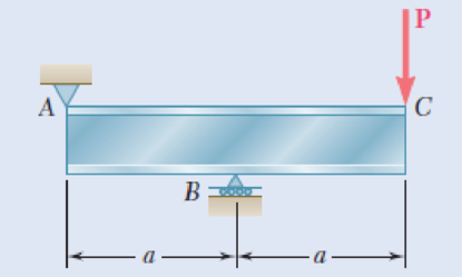
An overhanging W920 × 449 rolled-steel beam supports a load P as shown. Knowing that P = 700 kN, a = 2.5 m, and σall = 100 MPa, determine (a) the maximum value of the normal stress σm in the beam, (b) the maximum value of the principal stress σmax at the junction of the flange and web, (c) whether the specified shape is acceptable as far as these two stresses are concerned.
Fig. P8.3
Expert Solution & Answer
Want to see the full answer?
Check out a sample textbook solution
Students have asked these similar questions
The rigid beam BC is supported by rods (1) and (2). The cross-sectional area of rod (1) is 9 mm². The cross-sectional area of rod (2) is 18
mm². For a uniformly distributed load of w = 2.3 kN/m, determine the length a so that the normal stress is the same in each rod.
Assume L = 3.00 m.
(1)
B
Answer: a =
i
L
W
a
(2)
m
B
The steel tie bar shown is to be designed to carry a tension force of magnitude
P = 120 kN when bolted between double brackets at A and B. The bar will
be fabricated from 20-mm-thick plate stock. For the grade of steel to be used,
the maximum allowable stresses are: o = 175 MPa, ↑ = 100 MPa, o,
350 MPa. Design the tie bar by determining the required values of (a) the
diameter d of the bolt, (b) the dimension b at each end of the bar, (c) the
dimension h of the bar.
An axial load P is supported by a short W8x40 column of cross-sectional area A=11.7 in? and is
distributed to a concrete foundation by a square plate as shown. Knowing that the average normal stress
in the column must not exceed 30ksi and that the bearing stress on the concrete foundation must not
exceed 3.0 ksi, determine the side "a" of the plate that will provide the most economical and safe
design.
Chapter 8 Solutions
Mechanics of Materials, 7th Edition
Ch. 8.2 - A W10 = 39 rolled-steel beam supports a load P as...Ch. 8.2 - Solve Prob. 8.1, assuming that P = 22.5 kips and a...Ch. 8.2 - An overhanging W920 449 rolled-steel beam...Ch. 8.2 - Solve Prob. 8.3, assuming that P = 850 kN and a =...Ch. 8.2 - 8.5 and 8.6 (a) Knowing that all = 160 MPa and all...Ch. 8.2 - 8.5 and 8.6 (a) Knowing that all = 160 MPa and all...Ch. 8.2 - 8.7 and 8.8 (a) Knowing that all = 24 ksi and all...Ch. 8.2 - 8.7 and 8.8 (a) Knowing that all = 24 ksi and all...Ch. 8.2 - 8.9 through 8.14 Each of the following problems...Ch. 8.2 - 8.9 through 8.14 Each of the following problems...
Ch. 8.2 - 8.9 through 8.14 Each of the following problems...Ch. 8.2 - Prob. 12PCh. 8.2 - 8.9 through 8.14 Each of the following problems...Ch. 8.2 - 8.9 through 8.14 Each of the following problems...Ch. 8.2 - Determine the smallest allowable diameter of the...Ch. 8.2 - Determine the smallest allowable diameter of the...Ch. 8.2 - Using the notation of Sec. 8.2 and neglecting the...Ch. 8.2 - The 4-kN force is parallel to the x axis, and the...Ch. 8.2 - The vertical force P1 and the horizontal force P2...Ch. 8.2 - The two 500-lb forces are vertical and the force P...Ch. 8.2 - Prob. 21PCh. 8.2 - Prob. 22PCh. 8.2 - The solid shaft AB rotates at 600 rpm and...Ch. 8.2 - The solid shaft AB rotates at 600 rpm and...Ch. 8.2 - The solid shafts ABC and DEF and the gears shown...Ch. 8.2 - Prob. 26PCh. 8.2 - Prob. 27PCh. 8.2 - Prob. 28PCh. 8.2 - The solid shaft AE rotates at 600 rpm and...Ch. 8.2 - The solid shaft AE rotates at 600 rpm and...Ch. 8.3 - Two 1.2-kip forces are applied to an L-shaped...Ch. 8.3 - Two 1.2-kip forces are applied to an L-shaped...Ch. 8.3 - The cantilever beam AB has a rectangular cross...Ch. 8.3 - 8.34 through 8.36 Member AB has a uniform...Ch. 8.3 - 8.34 through 8.36 Member AB has a uniform...Ch. 8.3 - 8.34 through 8.36 Member AB has a uniform...Ch. 8.3 - Prob. 37PCh. 8.3 - Two forces are applied to the pipe AB as shown....Ch. 8.3 - Several forces are applied to the pipe assembly...Ch. 8.3 - The steel pile AB has a 100-mm outer diameter and...Ch. 8.3 - Three forces are applied to a 4-in.-diameter plate...Ch. 8.3 - The steel pipe AB has a 72-mm outer diameter and a...Ch. 8.3 - A 13-kN force is applied as shown to the...Ch. 8.3 - A vertical force P of magnitude 60 lb is applied...Ch. 8.3 - Three forces are applied to the bar shown....Ch. 8.3 - Prob. 46PCh. 8.3 - Three forces are applied to the bar shown....Ch. 8.3 - Three forces are applied to the bar shown....Ch. 8.3 - Two forces are applied to the small post BD as...Ch. 8.3 - Two forces are applied to the small post BD as...Ch. 8.3 - Three forces are applied to the machine component...Ch. 8.3 - Prob. 52PCh. 8.3 - Three steel plates, each 13 mm thick, are welded...Ch. 8.3 - Three steel plates, each 13 mm thick, are welded...Ch. 8.3 - Two forces P1 and P2 are applied as shown in...Ch. 8.3 - Two forces P1 and P2 are applied as shown in...Ch. 8.3 - Prob. 57PCh. 8.3 - Four forces are applied to a W8 28 rolled-steel...Ch. 8.3 - A force P is applied to a cantilever beam by means...Ch. 8.3 - Prob. 60PCh. 8.3 - A 5-kN force P is applied to a wire that is...Ch. 8.3 - Knowing that the structural tube shown has a...Ch. 8.3 - The structural tube shown has a uniform wall...Ch. 8.3 - The structural tube shown has a uniform wall...Ch. 8 - (a) Knowing that all = 24 ksi and all = 14.5 ksi,...Ch. 8 - Neglecting the effect of fillets and of stress...Ch. 8 - Knowing that rods BC and CD are of diameter 24 mm...Ch. 8 - The solid shaft AB rotates at 450 rpm and...Ch. 8 - A 6-kip force is applied to the machine element AB...Ch. 8 - A thin strap is wrapped around a solid rod of...Ch. 8 - A close-coiled spring is made of a circular wire...Ch. 8 - Forces are applied at points A and B of the solid...Ch. 8 - Knowing that the bracket AB has a uniform...Ch. 8 - For the post and loading shown, determine the...Ch. 8 - Knowing that the structural tube shown has a...Ch. 8 - The cantilever beam AB will be installed so that...
Additional Engineering Textbook Solutions
Find more solutions based on key concepts
What is the importance of modeling in engineering? How are the mathematical models for engineering processes pr...
HEAT+MASS TRANSFER:FUND.+APPL.
Repeat Problem 4-6 except solve by the vector loop method.
DESIGN OF MACHINERY
Locate the centroid of the area. Prob. 9-17
INTERNATIONAL EDITION---Engineering Mechanics: Statics, 14th edition (SI unit)
Determine the velocity of block D if end A of the rope is pulled down with a speed of vA = 3 m/s.
Engineering Mechanics: Dynamics (14th Edition)
A windowmounted air conditioner removes 3.5kJ from the inside of a home using 1.75 kJ work input. How much ener...
EBK FUNDAMENTALS OF THERMODYNAMICS, ENH
Determine the length of the cantilevered beam so that the maximum bending stress in the beam is equivalent to t...
Mechanics of Materials (10th Edition)
Knowledge Booster


Learn more about
Need a deep-dive on the concept behind this application? Look no further. Learn more about this topic, mechanical-engineering and related others by exploring similar questions and additional content below.Similar questions
- The rigid beam BC is supported by rods (1) and (2). The cross-sectional area of rod (1) is 7 mm2. The cross-sectional area of rod (2) is 18 mm2. For a uniformly distributed load of w = 2.5 kN/m, determine the length a so that the normal stress is the same in each rod. Assume L = 3.10 m. D (1) B |C aarrow_forwardAn annular washer distributes the load P applied to a steel rod to a timber support. The rod's diameter is 22 mm, and the washer's inner diameter is 25 mm, which is larger than the hole's permissible outer diameter. Knowing that the axial normal stress in the steel rod is 35 MPa and the average bearing stress between the washer and the timber must not exceed 5 MPa, examine the smallest allowed outer diameter, d, of the washer. %3D %3D +22 mm P Figure 4arrow_forwardThe rigid beam BC is supported by rods (1) and (2). The cross-sectional area of rod (1) is 7 mm². The cross-sectional area of rod (2) is 19 mm². For a uniformly distributed load of w = 2.0 kN/m, determine the length a so that the normal stress is the same in each rod. Assume L = 5.45 m. D (1) (2) W B Answer: a = i L a marrow_forward
- The rigid beam BC is supported by rods (1) and (2). The cross-sectional area of rod (1) is 7 mm2. The cross-sectional area of rod (2) is 18 mm2. For a uniformly distributed load of w = 2.7 kN/m, determine the length a so that the normal stress is the same in each rod. Assume L = 5.65 m.arrow_forwardProblem 04.103 - Steel W-beam loaded with up to three axial loads As many as three axial loads, each of magnitude P= 50 kN, can be applied to the end of a W200 × 31.1 rolled-steel shape. 80 mm- -80 mm 777 Problem 04.103.b - Stress in a flange when only two axial loads are applied Determine the stress at point A if loads are applied at points 1 and 2 only. The stress at point A is MPa.arrow_forward5. The load P applied to a steel rod is distributed to a timber support by an annular washer. The diameter of the rod is 22 mm and the inner diameter of the washer is 25 mm, which is slightly larger than the diameter of the hole. Determine the smallest allowable outer diameter d of the washer, knowing that the axial normal stress in the steel rod is 35 MPa and the average bearing stress between the washer and the timber must not exceed 5 MPa. - 22 mmarrow_forward
- The rectangular bar has a width of w = 3.00 in. and a thickness of t = 1.50 in. The normal stress on plane AB of the rectangular block shown is 6 ksi (C) when the load Pis applied. Assume a = 3 and b = 4. Determine (a) the magnitude of load P. (b) the shear stress on plane AB. (c) the maximum normal and shear stresses in the block at any possible orientation. A P b. B Answers: (а) Р- kips (b) Tnt = ksi (c) Omax ksi ksi Tmax =arrow_forwardThe rectangular bar has a width of w = 3.50 in. and a thickness of t = 1.50 in. The normal stress on plane AB of the rectangular block shown is 6 ksi (C) when the load Pis applied. Assume a = 4 and b = 5. Determine (a) the magnitude of load P. (b) the shear stress on plane AB. (c) the maximum normal and shear stresses in the block at any possible orientation. P B Answers: (а) Р- i kips (b) Tự = i ksi (c) Omax = i ksi Tmax i ksiarrow_forward6. Link BD consists of a single bar 30 mm wide and 12 mm thick. Knowing that each pin has a 10 mm diameter, determine the maximum value of the average normal stress in link BD if (a) 0 = 0°, (b) 0 = 90°. 150 m 00 mm 5B Page 2 of 3arrow_forward
- A timber beam AB of length L and rectangular cross section carries a single concentrated load P at its midpoint C. (a) Show that the ratio Tm/ m of the maximum values of the shearing and normal stresses in the beam is equal to h/2L, where h and L are, respectively, the depth and the length of the beam. (b) Determine the depth h and the width b of the beam, knowing that L = 2 m, P = 40 kN, 7m = 960 kPa, and om = 12 MPa.arrow_forward3. A solid bar having a diameter of 160 mm is to be replaced by a rectangular tube having cross- sectional area of 150 mm x 310 mm to the median line of the cross-section. (a) Determine the required thickness of the tube so that the maximum shear stress in the tube will not exceed the maximum shear stress in the solid bar. (b) Determine the shear stress in the tube . If it is subjected to a torque T = 15 kN-m and a thickness of 10 mm. and (c) Determine the angle of twist in degrees of the tube if the length of the tube is 1000 mm and the shear modulus is 75 GPa. Thickness of the tube is 10 mm and the torque T = 15 kN-m.arrow_forward| 275 kN (a) Knowing that ol =160 MPa and ra =100 MPa, select the most economical metric wide-flange shape that should be used to support the loading shown. (b) Determine the values to be expected for 275 kN om, Tm, and the principal stress omax at the junction of a flange and B D -3.6 m- 1.5 m 1.5 m the web of the selected beam. For (b) check at Points B and Carrow_forward
arrow_back_ios
SEE MORE QUESTIONS
arrow_forward_ios
Recommended textbooks for you
 Elements Of ElectromagneticsMechanical EngineeringISBN:9780190698614Author:Sadiku, Matthew N. O.Publisher:Oxford University Press
 Mechanics of Materials (10th Edition)Mechanical EngineeringISBN:9780134319650Author:Russell C. HibbelerPublisher:PEARSON
 Thermodynamics: An Engineering ApproachMechanical EngineeringISBN:9781259822674Author:Yunus A. Cengel Dr., Michael A. BolesPublisher:McGraw-Hill Education
 Control Systems EngineeringMechanical EngineeringISBN:9781118170519Author:Norman S. NisePublisher:WILEY
 Mechanics of Materials (MindTap Course List)Mechanical EngineeringISBN:9781337093347Author:Barry J. Goodno, James M. GerePublisher:Cengage Learning
 Engineering Mechanics: StaticsMechanical EngineeringISBN:9781118807330Author:James L. Meriam, L. G. Kraige, J. N. BoltonPublisher:WILEY
Elements Of Electromagnetics
Mechanical Engineering
ISBN:9780190698614
Author:Sadiku, Matthew N. O.
Publisher:Oxford University Press
Mechanics of Materials (10th Edition)
Mechanical Engineering
ISBN:9780134319650
Author:Russell C. Hibbeler
Publisher:PEARSON
Thermodynamics: An Engineering Approach
Mechanical Engineering
ISBN:9781259822674
Author:Yunus A. Cengel Dr., Michael A. Boles
Publisher:McGraw-Hill Education
Control Systems Engineering
Mechanical Engineering
ISBN:9781118170519
Author:Norman S. Nise
Publisher:WILEY
Mechanics of Materials (MindTap Course List)
Mechanical Engineering
ISBN:9781337093347
Author:Barry J. Goodno, James M. Gere
Publisher:Cengage Learning
Engineering Mechanics: Statics
Mechanical Engineering
ISBN:9781118807330
Author:James L. Meriam, L. G. Kraige, J. N. Bolton
Publisher:WILEY
Everything About COMBINED LOADING in 10 Minutes! Mechanics of Materials; Author: Less Boring Lectures;https://www.youtube.com/watch?v=N-PlI900hSg;License: Standard youtube license