
Mechanics of Materials, 7th Edition
7th Edition
ISBN: 9780073398235
Author: Ferdinand P. Beer, E. Russell Johnston Jr., John T. DeWolf, David F. Mazurek
Publisher: McGraw-Hill Education
expand_more
expand_more
format_list_bulleted
Concept explainers
Videos
Textbook Question
Chapter 8.3, Problem 35P
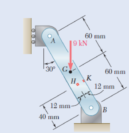
8.34 through 8.36 Member AB has a uniform rectangular cross section of 10 × 24 mm. For the loading shown, determine the normal and shearing stresses at (a) point H, (b) point K.
Fig. P8.35
Expert Solution & Answer
Want to see the full answer?
Check out a sample textbook solution
Students have asked these similar questions
7. Knowing that 0=40° and P=9 kN, determine (a) the smallest allowable diameter of the pin at
Bif the average shearing stress in the pin is not exceed 120 MPa, (b) the corresponding average
bearing stress in the member AB at B, (c) the corresponding average bearing stress in each of the
support brackets at B.
P
16 mm
750 mm
750 mm
50 mm-
12 inm
An open-link chain is obtained by bending low-carbon steel rods of 0.5-in. diameter into the shape shown (Fig. ). Knowing that the chain carries a load of 160 lb, determine (a) the largest tensile and compressive stresses in the straight portion of a link, (b) the distance between the cen-troidal and the neutral axis of a cross section
Problem 8.5 A circular ring is subjected to a pull of 15 kN. The
ring is of T-section as shown in Fig. 8.12 and the internal radius is 10
cm. Determine the maximum and minimum stresses in the ring.
2cm
12cm
10cm
2
cm
Fig. 8.12
Chapter 8 Solutions
Mechanics of Materials, 7th Edition
Ch. 8.2 - A W10 = 39 rolled-steel beam supports a load P as...Ch. 8.2 - Solve Prob. 8.1, assuming that P = 22.5 kips and a...Ch. 8.2 - An overhanging W920 449 rolled-steel beam...Ch. 8.2 - Solve Prob. 8.3, assuming that P = 850 kN and a =...Ch. 8.2 - 8.5 and 8.6 (a) Knowing that all = 160 MPa and all...Ch. 8.2 - 8.5 and 8.6 (a) Knowing that all = 160 MPa and all...Ch. 8.2 - 8.7 and 8.8 (a) Knowing that all = 24 ksi and all...Ch. 8.2 - 8.7 and 8.8 (a) Knowing that all = 24 ksi and all...Ch. 8.2 - 8.9 through 8.14 Each of the following problems...Ch. 8.2 - 8.9 through 8.14 Each of the following problems...
Ch. 8.2 - 8.9 through 8.14 Each of the following problems...Ch. 8.2 - Prob. 12PCh. 8.2 - 8.9 through 8.14 Each of the following problems...Ch. 8.2 - 8.9 through 8.14 Each of the following problems...Ch. 8.2 - Determine the smallest allowable diameter of the...Ch. 8.2 - Determine the smallest allowable diameter of the...Ch. 8.2 - Using the notation of Sec. 8.2 and neglecting the...Ch. 8.2 - The 4-kN force is parallel to the x axis, and the...Ch. 8.2 - The vertical force P1 and the horizontal force P2...Ch. 8.2 - The two 500-lb forces are vertical and the force P...Ch. 8.2 - Prob. 21PCh. 8.2 - Prob. 22PCh. 8.2 - The solid shaft AB rotates at 600 rpm and...Ch. 8.2 - The solid shaft AB rotates at 600 rpm and...Ch. 8.2 - The solid shafts ABC and DEF and the gears shown...Ch. 8.2 - Prob. 26PCh. 8.2 - Prob. 27PCh. 8.2 - Prob. 28PCh. 8.2 - The solid shaft AE rotates at 600 rpm and...Ch. 8.2 - The solid shaft AE rotates at 600 rpm and...Ch. 8.3 - Two 1.2-kip forces are applied to an L-shaped...Ch. 8.3 - Two 1.2-kip forces are applied to an L-shaped...Ch. 8.3 - The cantilever beam AB has a rectangular cross...Ch. 8.3 - 8.34 through 8.36 Member AB has a uniform...Ch. 8.3 - 8.34 through 8.36 Member AB has a uniform...Ch. 8.3 - 8.34 through 8.36 Member AB has a uniform...Ch. 8.3 - Prob. 37PCh. 8.3 - Two forces are applied to the pipe AB as shown....Ch. 8.3 - Several forces are applied to the pipe assembly...Ch. 8.3 - The steel pile AB has a 100-mm outer diameter and...Ch. 8.3 - Three forces are applied to a 4-in.-diameter plate...Ch. 8.3 - The steel pipe AB has a 72-mm outer diameter and a...Ch. 8.3 - A 13-kN force is applied as shown to the...Ch. 8.3 - A vertical force P of magnitude 60 lb is applied...Ch. 8.3 - Three forces are applied to the bar shown....Ch. 8.3 - Prob. 46PCh. 8.3 - Three forces are applied to the bar shown....Ch. 8.3 - Three forces are applied to the bar shown....Ch. 8.3 - Two forces are applied to the small post BD as...Ch. 8.3 - Two forces are applied to the small post BD as...Ch. 8.3 - Three forces are applied to the machine component...Ch. 8.3 - Prob. 52PCh. 8.3 - Three steel plates, each 13 mm thick, are welded...Ch. 8.3 - Three steel plates, each 13 mm thick, are welded...Ch. 8.3 - Two forces P1 and P2 are applied as shown in...Ch. 8.3 - Two forces P1 and P2 are applied as shown in...Ch. 8.3 - Prob. 57PCh. 8.3 - Four forces are applied to a W8 28 rolled-steel...Ch. 8.3 - A force P is applied to a cantilever beam by means...Ch. 8.3 - Prob. 60PCh. 8.3 - A 5-kN force P is applied to a wire that is...Ch. 8.3 - Knowing that the structural tube shown has a...Ch. 8.3 - The structural tube shown has a uniform wall...Ch. 8.3 - The structural tube shown has a uniform wall...Ch. 8 - (a) Knowing that all = 24 ksi and all = 14.5 ksi,...Ch. 8 - Neglecting the effect of fillets and of stress...Ch. 8 - Knowing that rods BC and CD are of diameter 24 mm...Ch. 8 - The solid shaft AB rotates at 450 rpm and...Ch. 8 - A 6-kip force is applied to the machine element AB...Ch. 8 - A thin strap is wrapped around a solid rod of...Ch. 8 - A close-coiled spring is made of a circular wire...Ch. 8 - Forces are applied at points A and B of the solid...Ch. 8 - Knowing that the bracket AB has a uniform...Ch. 8 - For the post and loading shown, determine the...Ch. 8 - Knowing that the structural tube shown has a...Ch. 8 - The cantilever beam AB will be installed so that...
Knowledge Booster


Learn more about
Need a deep-dive on the concept behind this application? Look no further. Learn more about this topic, mechanical-engineering and related others by exploring similar questions and additional content below.Similar questions
- 1.4 kN - m PROBLEM 8.43 A 10-kN force and a 1.4-kN - m couple are applied at the top of the 65-mm diameter brass post shown. Determine the principal stresses and maximum shearing stress at (a) point H, (b) point K. 10 kN 240 mm Omax = 30.0 MPa O min =-30.0 MPa Tmax = 30.0 MPa Omax = 7.02 MPa Omin =-96.0 MPa Tmay =51.5 MPaarrow_forwardSECTION B(1) Question 1 The bell crank CBA is connected to a pin support B in double shear with 8-mm diameter pin B and to the 10-mm diameter rod CD. Knowing that the ultimate shearing stress is 110 MPa for the steel used in pin B and the ultimate normal stress is 230 MPa for the steel used in rod CD. Determine the maximum vertical force P that can be applied if an overall factor of safety of 1.5 is desired. 45% 300 mm B Figure 1 -450 mm-arrow_forward8.49 A 40-kN axial load is applied to a short wooden post that is sup- ported by a concrete footing resting on undisturbed soil. Deter- mine (a) the maximum bearing stress on the concrete footing, (b) the size of the footing for which the average bearing stress in the soil is 145 kPa. |P = 40 kN 120 mm 100 mm Fig. P8.49arrow_forward
- PROBLEM 7.26 0.2 m The axle of an automobile is acted upon by the forces and couple shown. Knowing that the diameter of the solid axle is 32 mm, determine (a) the principal planes and principal stresses at point H located on top of the axle, (b) the maximum shearing stress at the same point. 3 kN 350 N- m 3 kN Omax = 18.67 MPa = -158,5 MPa O minarrow_forwardTwo links BF are made of steel with a 450-MPa ultimate normal stress and has a 6x12–mm uniform rectangular cross section. Links BF are connected to members ABD and CDEF by 8-mm diameter pins; ABD and CDEF are connected together by a 10-mm diameter pin; CDEF is connected to the support by a 10-mm diameter pin; all of the pins are made of steel with a 170 MPa ultimate shearing stress. Knowing that a factor of safety of 3 is desired, determine the largest load P that may be appliedarrow_forwardQue 5.6. A crane hook trapezoidal horizontal cross-section is 50 mm wide inside and 30 mm wide outside. Thickness of the section is 60 mm. The crane hook carries a vertical load of 20 kN whose line of action is 50 mm from the inside edge of the section. The center of curvature is 60 mm from the inside edge. Determine the maximum tensile and compressive stresses in the section.arrow_forward
- Problem 8.12 A bar of rectangular cross-section, with a width of 60 mm and a thickness of 40 mm, is bent in the shape of a horse shoe having a mean radius of 70 mm. Two equal and opposite forces of 10 kN each are applied at a distance of 12 cm from the centre line of the middle section so that they tend to straighten the rod. Find the maximum ten- sile and compressive stresses and construct a diagram showing the vari- ation of the normal stresses over the central section.arrow_forwardIn the structure shown, an 8-mm diameter pin is used at A, and 12- mm diameter pins are used at B and D. Knowing that the ultimate shearing stresses is 100 MPa at all connections and that the ultimate normal stress is 250 MPa in each of the two links joining B and D, determine the allowable load P if an overall factor of safety of 3.0 is desired.arrow_forwardTwo wooden members of uniform rectangular cross section of sides a = 100 mm and b = 60 mm are joined by a simple glued joint as shown. Knowing that the ultimate stresses for the joint are σU =1.26 MPa in tension and τU = 1.50 MPa in shear and that P =6 kN, determine the factor of safety for the joint when (a) α =20°,(b) α =35°, (c) α =45°. For each of these values of α, also determine whether the joint will fail in tension or in shear if P is increased until rupture occurs.arrow_forward
- Question 3. A 4 by 4-in. wood-post BC is connected to a 1-in. diameter steel eye-bar AB to form a hoist. A load of w = 7000 Ibs is applied at point B on the hoist. (a)Determine the axial stresses in members AB and BC. (b) Determine the cross shearing stress in the 1-in. diameter bolt at point A. STEEL V -7000 lb WOOD FIG. I Aarrow_forwardTwo wooden members of 80 *120-mm uniform rectangular cross section are joined by the simple glued scarf splice shown. Knowing that β=22° and that the maximum allowable stresses in the joint are, respectively, 400 kPa in tension (perpendicular to the splice) and 600 kPa in shear (parallel to the splice), determine the largest centric load P that can be appliedarrow_forwardTwo wooden members of uniform rectangular cross section are joined by the simple glued scarf splice shown. Knowing that P=11 kN,determine the normal and shearing stresses in the glued splice.arrow_forward
arrow_back_ios
SEE MORE QUESTIONS
arrow_forward_ios
Recommended textbooks for you
 Elements Of ElectromagneticsMechanical EngineeringISBN:9780190698614Author:Sadiku, Matthew N. O.Publisher:Oxford University Press
 Mechanics of Materials (10th Edition)Mechanical EngineeringISBN:9780134319650Author:Russell C. HibbelerPublisher:PEARSON
 Thermodynamics: An Engineering ApproachMechanical EngineeringISBN:9781259822674Author:Yunus A. Cengel Dr., Michael A. BolesPublisher:McGraw-Hill Education
 Control Systems EngineeringMechanical EngineeringISBN:9781118170519Author:Norman S. NisePublisher:WILEY
 Mechanics of Materials (MindTap Course List)Mechanical EngineeringISBN:9781337093347Author:Barry J. Goodno, James M. GerePublisher:Cengage Learning
 Engineering Mechanics: StaticsMechanical EngineeringISBN:9781118807330Author:James L. Meriam, L. G. Kraige, J. N. BoltonPublisher:WILEY
Elements Of Electromagnetics
Mechanical Engineering
ISBN:9780190698614
Author:Sadiku, Matthew N. O.
Publisher:Oxford University Press
Mechanics of Materials (10th Edition)
Mechanical Engineering
ISBN:9780134319650
Author:Russell C. Hibbeler
Publisher:PEARSON
Thermodynamics: An Engineering Approach
Mechanical Engineering
ISBN:9781259822674
Author:Yunus A. Cengel Dr., Michael A. Boles
Publisher:McGraw-Hill Education
Control Systems Engineering
Mechanical Engineering
ISBN:9781118170519
Author:Norman S. Nise
Publisher:WILEY
Mechanics of Materials (MindTap Course List)
Mechanical Engineering
ISBN:9781337093347
Author:Barry J. Goodno, James M. Gere
Publisher:Cengage Learning
Engineering Mechanics: Statics
Mechanical Engineering
ISBN:9781118807330
Author:James L. Meriam, L. G. Kraige, J. N. Bolton
Publisher:WILEY
Everything About COMBINED LOADING in 10 Minutes! Mechanics of Materials; Author: Less Boring Lectures;https://www.youtube.com/watch?v=N-PlI900hSg;License: Standard youtube license