
Concept explainers
Videos
8.9 through 8.14 Each of the following problems refers to a rolled-steel shape selected in a problem of Chap. 5 to support a given loading at a minimal cost while satisfying the requirement σm ≤ σall. For the selected design, determine (a) the actual value of σm in the beam, (b) the maximum value of the principal stress σmax at the junction of a flange and the web.
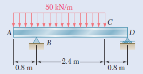
8.10 Loading of Prob. 5.74 and selected W250 × 28.4 shape.
Fig. P5.74
(a)
The actual value of
Answer to Problem 10P
The actual value of
Explanation of Solution
Given information:
Refer to problem 5.74 in chapter 5 in the textbook.
The rolled steel section is
Calculation:
Show the free-body diagram of the beam as in Figure 1.
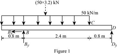
Determine the vertical reaction at point B by taking moment at point D.
Determine the vertical reaction at point D by resolving the vertical component of forces.
Shear force:
Show the calculation of shear force as follows;
Show the calculated shear force values as in Table 1.
| Location (x) m | Shear force (V) kN |
| A | 0 |
| B (Left) | –40 |
| B (Right) | 80 |
| C | –40 |
| D | –40 |
Plot the shear force diagram as in Figure 2.
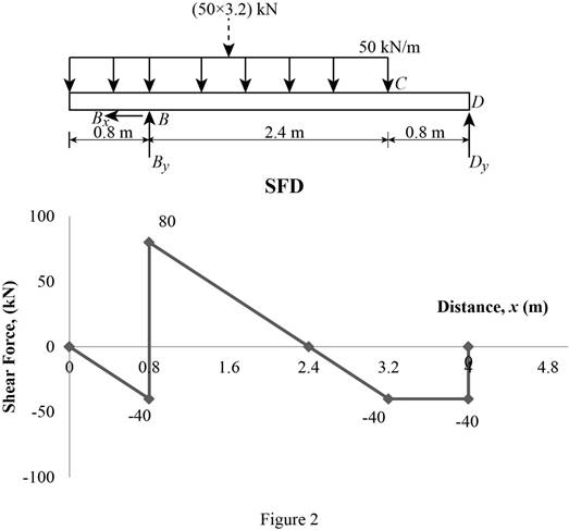
Location of the maximum bending moment:
The maximum bending moment occurs where the shear force changes sign.
Refer to Figure 2;
Use the method of similar triangle.
The maximum bending moment occurs at a distance 2.4 m from the left end of the beam.
Bending moment:
Show the calculation of the bending moment as follows;
Show the calculated bending moment values as in Table 2.
| Location (x) m | Bending moment (M) kN-m |
| A | 0 |
| B | –16 |
| Max BM | 48 |
| C | 32 |
| D | 0 |
Plot the bending moment diagram as in Figure 3.
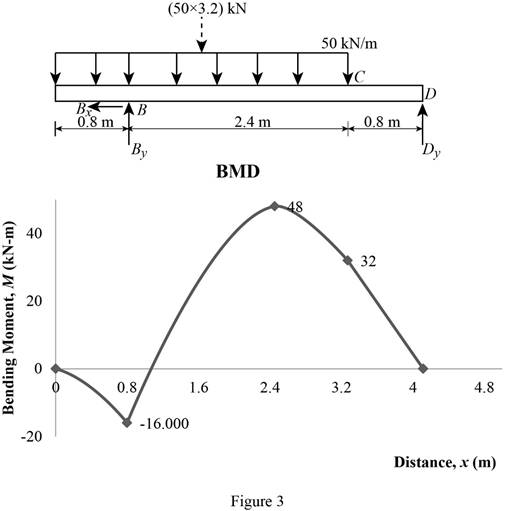
Refer to the Figure 3;
The maximum bending moment in the beam is
Write the section a property for a
| Dimension | Unit( |
| d | 259 mm |
| 102 mm | |
| 10.0 mm | |
| I | |
Here, d is depth of the section,
Find the value of C using the relation:
Substitute
Find the maximum value of normal stress
Here,
Substitute
Thus, the actual value of
(b)
The maximum value of principal stress
Answer to Problem 10P
The maximum value of principal stress
Explanation of Solution
Calculation:
Find the value
Here, c is the centroid and
Substitute
Find the area of flange
Here,
Substitute
Find the centroid of flange
Substitute
Find the first moment about neutral axis
Here,
Substitute
At midspan the value of
Find the maximum value of principal stress
Here, actual value of normal stress
Substitute
Find the shear stress
At midspan the value of
Therefore, the shear stress
At section C,
The shear force at point C is
The bending moment about C is
Find the value of
Substitute
Find the shear stress at b
Substitute
Find the maximum shearing stress (R) using the relation:
Here,
Substitute
Determine the maximum value of the principle stress using the relation:
Here, R is the maximum shearing stress and
Substitute
Based on results,
Select the maximum value of principal stress
Thus, the maximum value of principal stress
Want to see more full solutions like this?
Chapter 8 Solutions
Mechanics of Materials, 7th Edition


- Determine the maximum load F that can be applied at the free end of a 3 m cantilever beam of universal rolled-steel beam cross-section, 356 mm deep, with a moment of inertia of 142 × 106 mm4, if the allowable stress is 76 MPa.arrow_forwardA rectangular cross section steel column of length L, a fixed end at B and supports a concentric load at A as shown. Point A is restrained from moving in one of the vertical planes of symmetry of the column, but allows to move in the other plane by the use of two smooth and rounded fixed plates.(a) Determine the ratio a/b of the two sides of the cross section corresponding to the most efficient design against buckling.(b) Design the most efficient cross section for the column, knowing that L = 45 in., E = 10 x 106 psi, P = 20 kips, and that a factor of safety of 2.7 is required. Answers: (a) _______ (b) _______arrow_forwardEach of the two vertical links CF connecting the two horizontal members AD and EG has a 10x40-mm uniform rectangular cross section and is made of a steel with an ultimate strength in tension of 400 MPa,while each of the pins at C and F has a 20-mm diameter and is made of a steel with an ultimate strength in shear of 150 MPa. Determine the overall factor of safety for the links CF and the pins connecting them to the horizontal members.arrow_forward
- In the structure shown, an 8-mm-diameter pin is used at A, and 12-mm-diameter pins are used at B and D. Knowing that the ultimate shearing stress is 100 MPa at all connections and that the ultimate normal stress is 250 MPa in each of the two links joining B and D, determine the allowable load P if an overall factor of safety of 2.6 is desired.arrow_forwardA glue-laminated column of 3-m effective length is to be made from boards of 24 x 100-mm cross section. Knowing that for the grade of wood used, E= 11 GPa and the adjusted allowable stress for com-pression parallel to the grain is σC= 9 MPa, determine the number of boards that must be used to support the centric load shown when (a) P= 34 kN, (b) P= 17 kNarrow_forwardA 40-kN axial load is applied to a short wooden post that is supported by a concrete footing resting on undisturbed soil. Determine (a) the maximum bearing stress on the concrete footing, (b) the size of the footing for which the average bearing stress in the soil is 145 kPa.arrow_forward
- In the structure shown, an 8-mm diameter pin is used at A, and 12-mm diameter pins are used at B and D. Knowing that the ultimate shearing stress is 100 MPa at all connections and that the ultimate normal stress is 250 MPa in each of the two links joining B and D, determine the allowable load P if an overall factor ofsafety of 3.0 is desired.arrow_forwardEach of the three rolled-steel beams shown (numbered 1, 2, and 3) is to carry a 64-kip load uniformly distributed over the beam. Each of these beams has a 12-ft span and is to be supported by the two 24-ft rolled-steel girders AC and BD. The allowable normal stress for the steel used is 22.5 ksi. Determine the section modulus for each girder and select the most economical W shape for the two girders using the table given below. (Round the final answer to one decimal place.)arrow_forwardA 20 mm diameter rod BC has flat ends of 20 mm x 40 mm rectangular cross section, while the boom AB has a 30 x 50 mm rectangular cross section and is fitted with a clevis at the end B. Both members are connected at B by a pin from which the 30 kN load is suspended by means of a U-Shaped bracket. Boom AB is supported at A by a pin fitted into a double bracket, while rod BC is connected at C to a single bracket. All pins are 25 mm diameter. Determine the normal stresses in members AB and BC; shearing stresses and bearing stresses at A, B and C.arrow_forward
- Solve Prob A rod consisting of two cylindrical portions AB and BC is restrained at both ends. Portion AB is made of steel (Es5 29 3 106 psi, αs5 6.5 3 10–6/°F) and portion BC is made of aluminum (Ea5 10.4 3 106psi, αa5 13.3 3 10–6/°F). Knowing that the rod is initially unstressed, determine (a) the normal stresses induced in portions AB and BC by a temperature rise of 70°F, (b) the corresponding deflection of point B assuming that portion AB of the composite rod is made of aluminum and portion BC is made of steel.arrow_forwardTwo links BF are made of steel with a 450-MPa ultimate normal stress and has a 6x12–mm uniform rectangular cross section. Links BF are connected to members ABD and CDEF by 8-mm diameter pins; ABD and CDEF are connected together by a 10-mm diameter pin; CDEF is connected to the support by a 10-mm diameter pin; all of the pins are made of steel with a 170 MPa ultimate shearing stress. Knowing that a factor of safety of 3 is desired, determine the largest load P that may be appliedarrow_forwardA sawn lumber column with a 7.5* 5.5-in. cross section has an 18-ft effective length. Knowing that for the grade of wood used the adjusted allowable stress for compression parallel to the grain isσC= 1200 psi and that the adjusted modulus E= 470 *103 psi, determine the maximum allowable centric load for the column.arrow_forward
 Elements Of ElectromagneticsMechanical EngineeringISBN:9780190698614Author:Sadiku, Matthew N. O.Publisher:Oxford University Press
 Mechanics of Materials (10th Edition)Mechanical EngineeringISBN:9780134319650Author:Russell C. HibbelerPublisher:PEARSON
 Thermodynamics: An Engineering ApproachMechanical EngineeringISBN:9781259822674Author:Yunus A. Cengel Dr., Michael A. BolesPublisher:McGraw-Hill Education
 Control Systems EngineeringMechanical EngineeringISBN:9781118170519Author:Norman S. NisePublisher:WILEY
 Mechanics of Materials (MindTap Course List)Mechanical EngineeringISBN:9781337093347Author:Barry J. Goodno, James M. GerePublisher:Cengage Learning
 Engineering Mechanics: StaticsMechanical EngineeringISBN:9781118807330Author:James L. Meriam, L. G. Kraige, J. N. BoltonPublisher:WILEY