
Mechanics of Materials, 7th Edition
7th Edition
ISBN: 9780073398235
Author: Ferdinand P. Beer, E. Russell Johnston Jr., John T. DeWolf, David F. Mazurek
Publisher: McGraw-Hill Education
expand_more
expand_more
format_list_bulleted
Concept explainers
Videos
Textbook Question
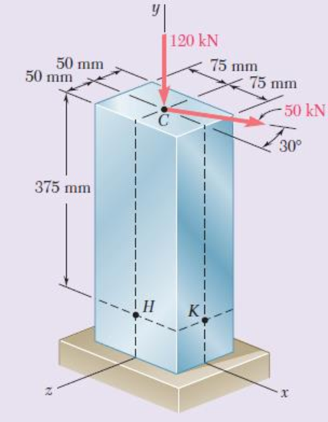
Chapter 8, Problem 74RP
For the post and loading shown, determine the principal stresses, principal planes, and maximum shearing stress at point H.
Fig. P8.74
Expert Solution & Answer
Want to see the full answer?
Check out a sample textbook solution
Students have asked these similar questions
Problem #6.
A state of plane stress is shown
b.) Determine the maximum in plane shear stress, in ksi
Y
т
6,000 psi
8,000 psi
4,000 psi
Three forces are applied to the cantilever beam shown. Determine the principal stresses and the maximum
shearing stress at point H.
4 in.
3 in.
2 kips
24 kips
Fig. P8.49
Answer
0.413 ksi, -0.0378 ksi; 0.225 ksi.
3 kips
Late
2 in.
15 in.
K
4 in.
T
5 in.
7 in.
6 in.
Problem #3
A block of steel with a rectangular cross-section of width 50 mm and height 100 mm is resting on
an inclined plane at an angle of 30 degrees to the horizontal. Determine the normal stress and the
shearing stress developed in the block if a force of 10 kN is applied to the block perpendicular to
the horizontal plane.
Chapter 8 Solutions
Mechanics of Materials, 7th Edition
Ch. 8.2 - A W10 = 39 rolled-steel beam supports a load P as...Ch. 8.2 - Solve Prob. 8.1, assuming that P = 22.5 kips and a...Ch. 8.2 - An overhanging W920 449 rolled-steel beam...Ch. 8.2 - Solve Prob. 8.3, assuming that P = 850 kN and a =...Ch. 8.2 - 8.5 and 8.6 (a) Knowing that all = 160 MPa and all...Ch. 8.2 - 8.5 and 8.6 (a) Knowing that all = 160 MPa and all...Ch. 8.2 - 8.7 and 8.8 (a) Knowing that all = 24 ksi and all...Ch. 8.2 - 8.7 and 8.8 (a) Knowing that all = 24 ksi and all...Ch. 8.2 - 8.9 through 8.14 Each of the following problems...Ch. 8.2 - 8.9 through 8.14 Each of the following problems...
Ch. 8.2 - 8.9 through 8.14 Each of the following problems...Ch. 8.2 - Prob. 12PCh. 8.2 - 8.9 through 8.14 Each of the following problems...Ch. 8.2 - 8.9 through 8.14 Each of the following problems...Ch. 8.2 - Determine the smallest allowable diameter of the...Ch. 8.2 - Determine the smallest allowable diameter of the...Ch. 8.2 - Using the notation of Sec. 8.2 and neglecting the...Ch. 8.2 - The 4-kN force is parallel to the x axis, and the...Ch. 8.2 - The vertical force P1 and the horizontal force P2...Ch. 8.2 - The two 500-lb forces are vertical and the force P...Ch. 8.2 - Prob. 21PCh. 8.2 - Prob. 22PCh. 8.2 - The solid shaft AB rotates at 600 rpm and...Ch. 8.2 - The solid shaft AB rotates at 600 rpm and...Ch. 8.2 - The solid shafts ABC and DEF and the gears shown...Ch. 8.2 - Prob. 26PCh. 8.2 - Prob. 27PCh. 8.2 - Prob. 28PCh. 8.2 - The solid shaft AE rotates at 600 rpm and...Ch. 8.2 - The solid shaft AE rotates at 600 rpm and...Ch. 8.3 - Two 1.2-kip forces are applied to an L-shaped...Ch. 8.3 - Two 1.2-kip forces are applied to an L-shaped...Ch. 8.3 - The cantilever beam AB has a rectangular cross...Ch. 8.3 - 8.34 through 8.36 Member AB has a uniform...Ch. 8.3 - 8.34 through 8.36 Member AB has a uniform...Ch. 8.3 - 8.34 through 8.36 Member AB has a uniform...Ch. 8.3 - Prob. 37PCh. 8.3 - Two forces are applied to the pipe AB as shown....Ch. 8.3 - Several forces are applied to the pipe assembly...Ch. 8.3 - The steel pile AB has a 100-mm outer diameter and...Ch. 8.3 - Three forces are applied to a 4-in.-diameter plate...Ch. 8.3 - The steel pipe AB has a 72-mm outer diameter and a...Ch. 8.3 - A 13-kN force is applied as shown to the...Ch. 8.3 - A vertical force P of magnitude 60 lb is applied...Ch. 8.3 - Three forces are applied to the bar shown....Ch. 8.3 - Prob. 46PCh. 8.3 - Three forces are applied to the bar shown....Ch. 8.3 - Three forces are applied to the bar shown....Ch. 8.3 - Two forces are applied to the small post BD as...Ch. 8.3 - Two forces are applied to the small post BD as...Ch. 8.3 - Three forces are applied to the machine component...Ch. 8.3 - Prob. 52PCh. 8.3 - Three steel plates, each 13 mm thick, are welded...Ch. 8.3 - Three steel plates, each 13 mm thick, are welded...Ch. 8.3 - Two forces P1 and P2 are applied as shown in...Ch. 8.3 - Two forces P1 and P2 are applied as shown in...Ch. 8.3 - Prob. 57PCh. 8.3 - Four forces are applied to a W8 28 rolled-steel...Ch. 8.3 - A force P is applied to a cantilever beam by means...Ch. 8.3 - Prob. 60PCh. 8.3 - A 5-kN force P is applied to a wire that is...Ch. 8.3 - Knowing that the structural tube shown has a...Ch. 8.3 - The structural tube shown has a uniform wall...Ch. 8.3 - The structural tube shown has a uniform wall...Ch. 8 - (a) Knowing that all = 24 ksi and all = 14.5 ksi,...Ch. 8 - Neglecting the effect of fillets and of stress...Ch. 8 - Knowing that rods BC and CD are of diameter 24 mm...Ch. 8 - The solid shaft AB rotates at 450 rpm and...Ch. 8 - A 6-kip force is applied to the machine element AB...Ch. 8 - A thin strap is wrapped around a solid rod of...Ch. 8 - A close-coiled spring is made of a circular wire...Ch. 8 - Forces are applied at points A and B of the solid...Ch. 8 - Knowing that the bracket AB has a uniform...Ch. 8 - For the post and loading shown, determine the...Ch. 8 - Knowing that the structural tube shown has a...Ch. 8 - The cantilever beam AB will be installed so that...
Knowledge Booster


Learn more about
Need a deep-dive on the concept behind this application? Look no further. Learn more about this topic, mechanical-engineering and related others by exploring similar questions and additional content below.Similar questions
- Problem 4 The steel pipe AB has a 102-mam outer diameter and a 6-mm wall thickness. Knowing that arm CD is rigidly attached to the pipe, determine the principal stresses and the maximum shearing stress at point K. And then show stress on Mohr's circle. 200 mm 6 mm B H D 51 mm 150 mm xarrow_forward1.4 kN - m PROBLEM 8.43 A 10-kN force and a 1.4-kN - m couple are applied at the top of the 65-mm diameter brass post shown. Determine the principal stresses and maximum shearing stress at (a) point H, (b) point K. 10 kN 240 mm Omax = 30.0 MPa O min =-30.0 MPa Tmax = 30.0 MPa Omax = 7.02 MPa Omin =-96.0 MPa Tmay =51.5 MPaarrow_forwardProblem #6a A state of plane stress is shown a.) Determine the maximum principle stress, in ksi 6,000 psi 8,000 psi 4,000 psiarrow_forward
- Problem 9.83 Determine the principal stress in ksi Determine the absolute maximum shear stress in ksi.arrow_forwardPROBLEM 8.40 A thin strap is wrapped around a solid rod of radius c= 20 mm as shown. Knowing that I = 100 mm and F = 5 kN, determine the normal and shearing stresses at (a) point H, (b) point K. o = 79.6 MPa T=7.96 MPa O =0 T=13.26 MPaarrow_forward60 MPa PROBLEM 7.3 45 MPa For the given state of stress, determine the normal and shearing stresses exerted on the oblique face of the shaded triangular element shown. Use a method of 120 MPA analysis based on the equilibrium of that element, as was done in the 70° derivations of Sec. 7.2. O=14.19 MPa T = 15.19 MPaarrow_forward
- For the state of plane stress shown in Fig. (1), determine:(a) the largest value of (σy) for which the maximum allowable shearing stress is equal to (62) MPa.(b) the principal stresses and the orientation of the principal planes.(c) Confirm your answer by means of a Mohr’s stress circle diagram and from the diagram determine the magnitude of the normal stress on a plane inclined at 20° counterclockwise to the plane on which the 50 MPa stress acts.arrow_forwardProblem 2. Three loads are applied to the short rectangular post shown In Fig. 2(a). The cross- sectional dimensions of the post are shown in Fig. 2(b). Determine: Me (a) The normal and shear stresses and points H and K; (b) The principal stresses and maximum in-plane shear stress at point H, and show the orientation of theses stresses in an appropriate sketch. No. M2 y 50 mm 210 kN %3D 120 mm (Naー 75 mm K 65 kN 30 mm 95 kN 160 mm 150 mm 30 mm Y-axis is the w to the sectin paimt Hond E امقره Fig. 2(b) 文 Section Proputics A= 120 X160=19200 mm Lx=160 - 40960000 mm-4094r L= 160x128 5KNス50 m-) %3D %3D = 23040000mm'= 23; 40Xlʻmm7 Int Faicesarrow_forwardProblem 8.12 A bar of rectangular cross-section, with a width of 60 mm and a thickness of 40 mm, is bent in the shape of a horse shoe having a mean radius of 70 mm. Two equal and opposite forces of 10 kN each are applied at a distance of 12 cm from the centre line of the middle section so that they tend to straighten the rod. Find the maximum ten- sile and compressive stresses and construct a diagram showing the vari- ation of the normal stresses over the central section.arrow_forward
- Fig. 2 4. A steel shaft of diameter 50 mm and length 1.2 m (E = 210 GPa and v = 0.3) is loaded with multiple force system. At a point in the shaft, the state of stress relative to the x, y, z coordinate system was found to be: [600 0 T = 0 320 MPa -480 (a) Draw a cube element showing the stress components on each coordinate face (Hint: No vector lines for zero stresses; Warning: A stress element without reference axes will receive zero point). (b) From the given stress tensor, determine the values of (i) octahedral normal stress (Goct) and (ii) octahedral shear stress (toct). (c) From your answer in (b), determine (i) dilatational strain energy Udilat '); and (ii) deviatoric strain energy (Udist). (d) Find the total strain energy at the point.arrow_forwardA steel pipe of 300-mm outer diameter is fabricated from an 8-mm-thick plate by welding along a helix that forms an angle of 20° with a plane perpendicular to the axis of the pipe. Knowing that a 250-kN axial force P and a 12-kN-m torque T. each directed as shown, are applied to the pipe, determine the normal and in-plane shearing stresses in directions, respectively, normal and tangential to the weld. T The normal stress is - The shear stress is- Weld 20⁰ 8 mm MPa MPa.arrow_forwardProblem 8.5 A circular ring is subjected to a pull of 15 kN. The ring is of T-section as shown in Fig. 8.12 and the internal radius is 10 cm. Determine the maximum and minimum stresses in the ring. 2cm 12cm 10cm 2 cm Fig. 8.12arrow_forward
arrow_back_ios
SEE MORE QUESTIONS
arrow_forward_ios
Recommended textbooks for you
 Elements Of ElectromagneticsMechanical EngineeringISBN:9780190698614Author:Sadiku, Matthew N. O.Publisher:Oxford University Press
 Mechanics of Materials (10th Edition)Mechanical EngineeringISBN:9780134319650Author:Russell C. HibbelerPublisher:PEARSON
 Thermodynamics: An Engineering ApproachMechanical EngineeringISBN:9781259822674Author:Yunus A. Cengel Dr., Michael A. BolesPublisher:McGraw-Hill Education
 Control Systems EngineeringMechanical EngineeringISBN:9781118170519Author:Norman S. NisePublisher:WILEY
 Mechanics of Materials (MindTap Course List)Mechanical EngineeringISBN:9781337093347Author:Barry J. Goodno, James M. GerePublisher:Cengage Learning
 Engineering Mechanics: StaticsMechanical EngineeringISBN:9781118807330Author:James L. Meriam, L. G. Kraige, J. N. BoltonPublisher:WILEY
Elements Of Electromagnetics
Mechanical Engineering
ISBN:9780190698614
Author:Sadiku, Matthew N. O.
Publisher:Oxford University Press
Mechanics of Materials (10th Edition)
Mechanical Engineering
ISBN:9780134319650
Author:Russell C. Hibbeler
Publisher:PEARSON
Thermodynamics: An Engineering Approach
Mechanical Engineering
ISBN:9781259822674
Author:Yunus A. Cengel Dr., Michael A. Boles
Publisher:McGraw-Hill Education
Control Systems Engineering
Mechanical Engineering
ISBN:9781118170519
Author:Norman S. Nise
Publisher:WILEY
Mechanics of Materials (MindTap Course List)
Mechanical Engineering
ISBN:9781337093347
Author:Barry J. Goodno, James M. Gere
Publisher:Cengage Learning
Engineering Mechanics: Statics
Mechanical Engineering
ISBN:9781118807330
Author:James L. Meriam, L. G. Kraige, J. N. Bolton
Publisher:WILEY
Pressure Vessels Introduction; Author: Engineering and Design Solutions;https://www.youtube.com/watch?v=Z1J97IpFc2k;License: Standard youtube license