
Mechanics of Materials, 7th Edition
7th Edition
ISBN: 9780073398235
Author: Ferdinand P. Beer, E. Russell Johnston Jr., John T. DeWolf, David F. Mazurek
Publisher: McGraw-Hill Education
expand_more
expand_more
format_list_bulleted
Videos
Textbook Question
Chapter 8.2, Problem 4P
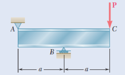
Solve Prob. 8.3, assuming that P = 850 kN and a = 2.0 m.
8.3 An overhanging W920 × 449 rolled-steel beam supports a load P as shown. Knowing that P = 700 kN, a = 2.5 m, and σall = 100 MPa, determine (a) the maximum value of the normal stress σm in the beam, (b) the maximum value of the principal stress σmax at the junction of the flange and web, (c) whether the specified shape is acceptable as far as these two stresses are concerned.
Fig. P8.3
Expert Solution & Answer
Want to see the full answer?
Check out a sample textbook solution
Students have asked these similar questions
c An overhanging W920×449 rolled-steel beam supports a load P as shown.
Knowing that P= 700 kN, a = 2.5 m, and oa =100 MPa, determine (a) the
maximum value of the normal stress o, in the beam, (b) the maximum value
of the principal stress omx at the junction of the flange and web, (c) whether
the specified shape is acceptable as far as these two stresses are concerned.
Homework
A timber beam AB of length L and rectangular cross section carries
a single concentrated load P at its midpoint C. (a) Show that the ratio
Tm/0, of the maximum values of the shearing and normal stresses in
the beam is equal to h/2L, where h and L are, respectively, the depth
and the length of the beam. (b) Determine the depth h and the width
b of the beam, knowing that L = 2 m, P = 40 kN, 7,m = 960 kPa,
and om
12 MPa.
%3D
L/2-
- L/2 16|-
В
Homework
A timber beam AB of length L and rectangular cross section carries
a single concentrated load P at its midpoint C. (a) Show that the ratio
Tm/Tm of the maximum values of the shearing and normal stresses in
the beam is equal to h/2L, where h and L are, respectively, the depth
and the length of the beam. (b) Determine the depth h and the width
b of the beam, knowing that L = 2 m, P = 40 KN, T, = 960 kPa,
and om = 12 MPa.
m
· L/2
C
- L/2·
A
В
Chapter 8 Solutions
Mechanics of Materials, 7th Edition
Ch. 8.2 - A W10 = 39 rolled-steel beam supports a load P as...Ch. 8.2 - Solve Prob. 8.1, assuming that P = 22.5 kips and a...Ch. 8.2 - An overhanging W920 449 rolled-steel beam...Ch. 8.2 - Solve Prob. 8.3, assuming that P = 850 kN and a =...Ch. 8.2 - 8.5 and 8.6 (a) Knowing that all = 160 MPa and all...Ch. 8.2 - 8.5 and 8.6 (a) Knowing that all = 160 MPa and all...Ch. 8.2 - 8.7 and 8.8 (a) Knowing that all = 24 ksi and all...Ch. 8.2 - 8.7 and 8.8 (a) Knowing that all = 24 ksi and all...Ch. 8.2 - 8.9 through 8.14 Each of the following problems...Ch. 8.2 - 8.9 through 8.14 Each of the following problems...
Ch. 8.2 - 8.9 through 8.14 Each of the following problems...Ch. 8.2 - Prob. 12PCh. 8.2 - 8.9 through 8.14 Each of the following problems...Ch. 8.2 - 8.9 through 8.14 Each of the following problems...Ch. 8.2 - Determine the smallest allowable diameter of the...Ch. 8.2 - Determine the smallest allowable diameter of the...Ch. 8.2 - Using the notation of Sec. 8.2 and neglecting the...Ch. 8.2 - The 4-kN force is parallel to the x axis, and the...Ch. 8.2 - The vertical force P1 and the horizontal force P2...Ch. 8.2 - The two 500-lb forces are vertical and the force P...Ch. 8.2 - Prob. 21PCh. 8.2 - Prob. 22PCh. 8.2 - The solid shaft AB rotates at 600 rpm and...Ch. 8.2 - The solid shaft AB rotates at 600 rpm and...Ch. 8.2 - The solid shafts ABC and DEF and the gears shown...Ch. 8.2 - Prob. 26PCh. 8.2 - Prob. 27PCh. 8.2 - Prob. 28PCh. 8.2 - The solid shaft AE rotates at 600 rpm and...Ch. 8.2 - The solid shaft AE rotates at 600 rpm and...Ch. 8.3 - Two 1.2-kip forces are applied to an L-shaped...Ch. 8.3 - Two 1.2-kip forces are applied to an L-shaped...Ch. 8.3 - The cantilever beam AB has a rectangular cross...Ch. 8.3 - 8.34 through 8.36 Member AB has a uniform...Ch. 8.3 - 8.34 through 8.36 Member AB has a uniform...Ch. 8.3 - 8.34 through 8.36 Member AB has a uniform...Ch. 8.3 - Prob. 37PCh. 8.3 - Two forces are applied to the pipe AB as shown....Ch. 8.3 - Several forces are applied to the pipe assembly...Ch. 8.3 - The steel pile AB has a 100-mm outer diameter and...Ch. 8.3 - Three forces are applied to a 4-in.-diameter plate...Ch. 8.3 - The steel pipe AB has a 72-mm outer diameter and a...Ch. 8.3 - A 13-kN force is applied as shown to the...Ch. 8.3 - A vertical force P of magnitude 60 lb is applied...Ch. 8.3 - Three forces are applied to the bar shown....Ch. 8.3 - Prob. 46PCh. 8.3 - Three forces are applied to the bar shown....Ch. 8.3 - Three forces are applied to the bar shown....Ch. 8.3 - Two forces are applied to the small post BD as...Ch. 8.3 - Two forces are applied to the small post BD as...Ch. 8.3 - Three forces are applied to the machine component...Ch. 8.3 - Prob. 52PCh. 8.3 - Three steel plates, each 13 mm thick, are welded...Ch. 8.3 - Three steel plates, each 13 mm thick, are welded...Ch. 8.3 - Two forces P1 and P2 are applied as shown in...Ch. 8.3 - Two forces P1 and P2 are applied as shown in...Ch. 8.3 - Prob. 57PCh. 8.3 - Four forces are applied to a W8 28 rolled-steel...Ch. 8.3 - A force P is applied to a cantilever beam by means...Ch. 8.3 - Prob. 60PCh. 8.3 - A 5-kN force P is applied to a wire that is...Ch. 8.3 - Knowing that the structural tube shown has a...Ch. 8.3 - The structural tube shown has a uniform wall...Ch. 8.3 - The structural tube shown has a uniform wall...Ch. 8 - (a) Knowing that all = 24 ksi and all = 14.5 ksi,...Ch. 8 - Neglecting the effect of fillets and of stress...Ch. 8 - Knowing that rods BC and CD are of diameter 24 mm...Ch. 8 - The solid shaft AB rotates at 450 rpm and...Ch. 8 - A 6-kip force is applied to the machine element AB...Ch. 8 - A thin strap is wrapped around a solid rod of...Ch. 8 - A close-coiled spring is made of a circular wire...Ch. 8 - Forces are applied at points A and B of the solid...Ch. 8 - Knowing that the bracket AB has a uniform...Ch. 8 - For the post and loading shown, determine the...Ch. 8 - Knowing that the structural tube shown has a...Ch. 8 - The cantilever beam AB will be installed so that...
Knowledge Booster


Learn more about
Need a deep-dive on the concept behind this application? Look no further. Learn more about this topic, mechanical-engineering and related others by exploring similar questions and additional content below.Similar questions
- An annular washer distributes the load P applied to a steel rod to a timber support. The rod's diameter is 22 mm, and the washer's inner diameter is 25 mm, which is larger than the hole's permissible outer diameter. Knowing that the axial normal stress in the steel rod is 35 MPa and the average bearing stress between the washer and the timber must not exceed 5 MPa, examine the smallest allowed outer diameter, d, of the washer. %3D %3D +22 mm P Figure 4arrow_forwardA 6 * 10-in. timber beam has been strengthened by bolting to it the steel straps shown. The modulus of elasticity is E= 1.5 *106 psi for the wood and E= 30 * 106 psi for the steel. Knowing that the beam is bent about a horizontal axis by a couple of moment 200 kip·in., determine the maximum stress in (a) the wood, (b) the steel.arrow_forwardL/4 D L/2 LA B A timber beam AB of length L and rectangular cross section carries a uniformly distributed load w and is supported as shown. (a) Show that the ratio of the maximum values of the shearing and normal stresses in the beam is equal to 2h/L, where h and L are, respectively, the depth and the length of the beam. (b) Determine the depth h and the width b of the beam, knowing that L = 5 m, w = 8 kN/m, Tm = 1.08 MPa, and om = 12 MPa.arrow_forward
- Knowing that the average normal stress in member EF of the Pratt bridge truss shown must not exceed 8.36 ksi for the given loading, determine the cross-sectional area (in sq. in) of this member that will yield the most economical and safe design if h = 14.2 ft and P = 87.28 kips.arrow_forwardQ1. (A). A 25mm square cross-section bar of length 300mm carries an axial compressive load of 50kN. Determine the stress set up in the bar and its change of length when the load is applied. For the bar material E= 200 GN/m². Q2. A beam AB, 1.2 m long, is simply-supported at its ends A and B and carries two concentrated loads, one of 10 kN at C, the other 15 kN at D. Point C is 0.4 m from A, point D is 1 m from A. Draw the S.F. and B.M. diagrams for the beam. Q3. A solid steel shaft (A) of 50 mm diameter rotates at 250 rev/min. Find the greatest power that can be transmitted for a limiting shearing stress of 60 MN/m2 in the steel.arrow_forward5. The load P applied to a steel rod is distributed to a timber support by an annular washer. The diameter of the rod is 22 mm and the inner diameter of the washer is 25 mm, which is slightly larger than the diameter of the hole. Determine the smallest allowable outer diameter d of the washer, knowing that the axial normal stress in the steel rod is 35 MPa and the average bearing stress between the washer and the timber must not exceed 5 MPa. - 22 mmarrow_forward
- A 6-x 10-in. timber beam has been strengthened by bolting two - x 2-in. steel straps to it as shown below. The moduli of elasticity are 1.5 x 10⁶ psi for the wood and 30 x 106 psi for the steel. Knowing that the beam is bent about a horizontal axis by a bending moment of 200 kip in, determine (a) The maximum flexural stress in the wood. (b) The maximum flexural stress in the steel. 10 in. T 6 in.. wood 2 x 3/8 in. steelarrow_forwardQI/Beams AB Problems, BC, and CD have the cross section shown and are pin-connected at B and C. Knowing that the allowable normal stress is +110 MPa in tension and -150 MPa in compression, (a) determine the largest permissible value of P (b) determine distance a. 12.5 mm -200 mm- 150 mm 24 m 2.4 m 2.4 m --l|- 12.5 mmarrow_forwardThe rigid beam BC is supported by rods (1) and (2). The cross-sectional area of rod (1) is 7 mm2. The cross-sectional area of rod (2) is 18 mm2. For a uniformly distributed load of w = 2.5 kN/m, determine the length a so that the normal stress is the same in each rod. Assume L = 3.10 m. D (1) B |C aarrow_forward
- The rigid beam BC is supported by rods (1) and (2). The cross-sectional area of rod (1) is 9 mm². The cross-sectional area of rod (2) is 18 mm². For a uniformly distributed load of w = 2.3 kN/m, determine the length a so that the normal stress is the same in each rod. Assume L = 3.00 m. (1) B Answer: a = i L W a (2) marrow_forwardKnowing that the average normal stress in member EF of the Pratt bridge truss shown must not exceed 8.56 ksi for the given loading, determine the cross-sectional area (in sq. in) of this member that will yield the most economical and safe design if h = 14.3 ft and P = 89.28 kips. detailed answer pls, need answer asaparrow_forwardThe 6 × 12-in. timber beam has been strengthened by bolting to it the steel reinforcement shown. The modulus of elasticity for wood is 1.8 × 10⁶ psi and for steel, 29 × 106 psi. Knowing that the beam is bent about a horizontal axis by a couple of moment M = 458 kip·in., determine the maximum stress in the wood and in the steel. The maximum compressive stress in the block of wood is ksi (include a negative sign). The maximum tensile stress in the steel is ksi.arrow_forward
arrow_back_ios
SEE MORE QUESTIONS
arrow_forward_ios
Recommended textbooks for you
 Elements Of ElectromagneticsMechanical EngineeringISBN:9780190698614Author:Sadiku, Matthew N. O.Publisher:Oxford University Press
 Mechanics of Materials (10th Edition)Mechanical EngineeringISBN:9780134319650Author:Russell C. HibbelerPublisher:PEARSON
 Thermodynamics: An Engineering ApproachMechanical EngineeringISBN:9781259822674Author:Yunus A. Cengel Dr., Michael A. BolesPublisher:McGraw-Hill Education
 Control Systems EngineeringMechanical EngineeringISBN:9781118170519Author:Norman S. NisePublisher:WILEY
 Mechanics of Materials (MindTap Course List)Mechanical EngineeringISBN:9781337093347Author:Barry J. Goodno, James M. GerePublisher:Cengage Learning
 Engineering Mechanics: StaticsMechanical EngineeringISBN:9781118807330Author:James L. Meriam, L. G. Kraige, J. N. BoltonPublisher:WILEY
Elements Of Electromagnetics
Mechanical Engineering
ISBN:9780190698614
Author:Sadiku, Matthew N. O.
Publisher:Oxford University Press
Mechanics of Materials (10th Edition)
Mechanical Engineering
ISBN:9780134319650
Author:Russell C. Hibbeler
Publisher:PEARSON
Thermodynamics: An Engineering Approach
Mechanical Engineering
ISBN:9781259822674
Author:Yunus A. Cengel Dr., Michael A. Boles
Publisher:McGraw-Hill Education
Control Systems Engineering
Mechanical Engineering
ISBN:9781118170519
Author:Norman S. Nise
Publisher:WILEY
Mechanics of Materials (MindTap Course List)
Mechanical Engineering
ISBN:9781337093347
Author:Barry J. Goodno, James M. Gere
Publisher:Cengage Learning
Engineering Mechanics: Statics
Mechanical Engineering
ISBN:9781118807330
Author:James L. Meriam, L. G. Kraige, J. N. Bolton
Publisher:WILEY
Mechanics of Materials Lecture: Beam Design; Author: UWMC Engineering;https://www.youtube.com/watch?v=-wVs5pvQPm4;License: Standard Youtube License