
Concept explainers
Videos
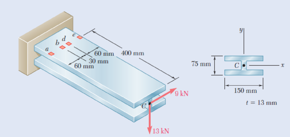
Three steel plates, each 13 mm thick, are welded together to form a cantilever beam. For the loading shown, determine the normal and shearing stresses at points d and e.
Fig. P8.53 and P8.54
The normal and shearing stress at point a and b.
Answer to Problem 54P
The normal stress at point d is
The shear stress at point d is
The normal stress at point e is
The shear stress at point e is
Explanation of Solution
Given information:
The thickness (t) of the steel plate is
Calculation:
Refer to Figure P8.51 in the textbook.
Forces at H are as follows:
The force in x direction,
The force in y direction,
The force in z direction,
Moments at H are as follows:
Find the moment about x axis as follows:
Find the moment about y axis as follows:
At point A:
Sketch the I section as shown in Figure 1.
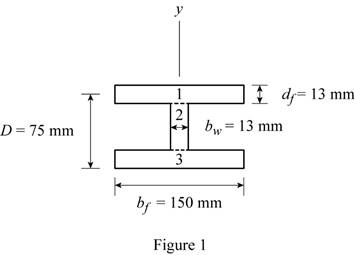
Refer to Figure 1.
Find the centroid section
Find the centroid section
Find the area of the section using the relation:
Here, b is the width and d is the depth of the flange and web respectively.
Refer to Figure 1.
Substitute
Find the moment of inertia
Substitute
Find the moment of inertia
Substitute
At point d:
Sketch the I section for point b as shown in Figure 2.
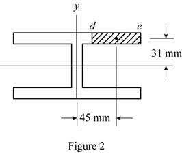
Refer to Figure 2.
Find the area of section (A) as follows:
Substitute
Refer to Figure 2.
The centroid of the
The centroid of the
Find the first moment area
Substitute
Find the first moment area
Substitute
Find the first moment area
The point e is located at edge. Since
The point e is located at edge. Since
Determine the normal stress at point d using the relation:
Here,
Substitute
Thus, the normal stress at point d is
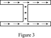
Determine the shear stress at point a due to
Substitute
Sketch the horizontal direction of shear stress as shown in figure 3.
Determine the shear stress at point a due to
Substitute
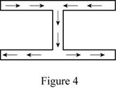
Sketch the vertical direction of shear stress as shown in figure 4.
Find the shear stress at point d using superposition method.
Thus, the shear stress at point d is
Determine the normal stress at point e using the relation:
Substitute
Thus, the normal stress at point b is
Determine the shear stress at point e using the relation:
The point e is located on edge.
The shear stress at point e is zero.
Want to see more full solutions like this?
Chapter 8 Solutions
Mechanics of Materials, 7th Edition


- A cast-iron tube is used to support a compressive load. Knowing that E5 10 3 106 psi and that the maximum allowable change in length is 0.025%, determine (a) the maximum normal stress in the tube, (b) the minimum wall thickness for a load of 1600 lb if the outside diameter of the tube is 2.0 in.arrow_forwardDetermine the shape of a fully stressed, simply supported beam that supportsa concentrated force at its center, Fig. 11–11a. The beam has a rectangularcross section of constant width b, and the allowable stress is sallow.arrow_forwardA compressive member of a structure is of 25 mm square cross-section and carries a load of 50 kN. Determine, from first principles, the normal, tangential, and resultant stresses on a plane inclined at 60° to the axis of the bar.arrow_forward
- The driveshaft of an automobile is being designed to transmit 238 hp at 3790 rpm. Determine the minimum diameter d required for a solid steel shaft if the allowable shear stress in the shaft is not to exceed 5700 psi.arrow_forwardIn the structure shown, an 8-mm diameter pin is used at A, and 12- mm diameter pins are used at B and D. Knowing that the ultimate shearing stresses is 100 MPa at all connections and that the ultimate normal stress is 250 MPa in each of the two links joining B and D, determine the allowable load P if an overall factor of safety of 3.0 is desired.arrow_forwardIn the steel structure shown, a 6-mm-diameter pin is used at C and10-mm-diameter pins are used at B and D. The ultimate shearing stress is 150 MPa at all connections, and the ultimate normal stress is 400 MPa in link BD. Knowing that a factor of safety of 3.0 is desired,determine the largest load P that can be applied at A. Note that link BD is not reinforced around the pin holes.arrow_forward
- In the steel structure shown, a 6-mm-diameter pin is used at C and 12-mm-diameter pins are used at B and D. The ultimate shearing stress is 150 MPa at all connections, and the ultimate normal stress is 350 MPa in link BD. Knowing that a factor of safety of 3.0 is desired, determine the largest load P that can be applied at A. Note that link BD is not reinforced around the pin holes. The largest load P that can be applied at A is kN.arrow_forwardIn the structure shown, an 8-mm-diameter pin is used at A, and 12-mm-diameter pins are used at B and D. Knowing that the ultimate shearing stress is 100 MPa at all connections and that the ultimate normal stress is 250 MPa in each of the two links joining B and D, determine the allowable load P if an overall factor of safety of 2.6 is desired.arrow_forwardA 40-kN axial load is applied to a short wooden post that is supported by a concrete footing resting on undisturbed soil. Determine (a) the maximum bearing stress on the concrete footing, (b) the size of the footing for which the average bearing stress in the soil is 145 kPa.arrow_forward
- A timber beam AB of length L and rectangular cross section carries a single concentrated load P at its midpoint C. (a) Show that the ratio Tm/ m of the maximum values of the shearing and normal stresses in the beam is equal to h/2L, where h and L are, respectively, the depth and the length of the beam. (b) Determine the depth h and the width b of the beam, knowing that L = 2 m, P = 40 kN, 7m = 960 kPa, and om = 12 MPa.arrow_forwardPart of a steel tube, 30mm external diameter and 6mm thick, is to be enlarged to form a compound tube of external diameter 40mm. Determine: The metal thickness of the enlarged section if the maximum shear stress is to be the same in both sections, when the compound tube is subjected to a torquearrow_forwardA spherical gas container made of steel has a 20-ft outer diameter and a wall thickness of 7/16 in. Knowing that the internal pressure is 75 psi, determine the maximum normal stress and the maximum shearing stress in the container.arrow_forward
 Elements Of ElectromagneticsMechanical EngineeringISBN:9780190698614Author:Sadiku, Matthew N. O.Publisher:Oxford University Press
 Mechanics of Materials (10th Edition)Mechanical EngineeringISBN:9780134319650Author:Russell C. HibbelerPublisher:PEARSON
 Thermodynamics: An Engineering ApproachMechanical EngineeringISBN:9781259822674Author:Yunus A. Cengel Dr., Michael A. BolesPublisher:McGraw-Hill Education
 Control Systems EngineeringMechanical EngineeringISBN:9781118170519Author:Norman S. NisePublisher:WILEY
 Mechanics of Materials (MindTap Course List)Mechanical EngineeringISBN:9781337093347Author:Barry J. Goodno, James M. GerePublisher:Cengage Learning
 Engineering Mechanics: StaticsMechanical EngineeringISBN:9781118807330Author:James L. Meriam, L. G. Kraige, J. N. BoltonPublisher:WILEY