
Mechanics of Materials, 7th Edition
7th Edition
ISBN: 9780073398235
Author: Ferdinand P. Beer, E. Russell Johnston Jr., John T. DeWolf, David F. Mazurek
Publisher: McGraw-Hill Education
expand_more
expand_more
format_list_bulleted
Videos
Textbook Question
Chapter 8, Problem 67RP
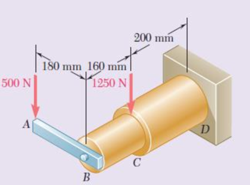
Knowing that rods BC and CD are of diameter 24 mm and 36 mm, respectively, determine the maximum shearing stress in each rod. Neglect the effect of fillets and of stress concentrations.
Fig. P8.66 and P8.67
Expert Solution & Answer
Want to see the full answer?
Check out a sample textbook solution
Students have asked these similar questions
TWO IDENTICAL LINKAGE-AND-HYDRAULIC-CYLINDER SYSTEMS CONTROL THE
POSITION OF THE FORKS OF A FORK-LIFT TRUCK. THE LOAD SUPPORTED BY
THEONE SYSTEM SHOWN IS 6750 N.
KNOWING THAT THE THICKNESS OF MEMBER BD IS 16 MM, DETERMINE (A)
THE AVERAGE SHEARING STRESS IN 13 MM DIAMETER PIN AT B,
(B) THE BEARING STRESS AT B IN MEMBER BD.
300 mm
300 mm
6.750 N
375 mm
400 mm 400 mm 500 mm
7. Knowing that 0=40° and P=9 kN, determine (a) the smallest allowable diameter of the pin at
Bif the average shearing stress in the pin is not exceed 120 MPa, (b) the corresponding average
bearing stress in the member AB at B, (c) the corresponding average bearing stress in each of the
support brackets at B.
P
16 mm
750 mm
750 mm
50 mm-
12 inm
For the assembly and loading of Prob. 8.8, determine (a) the average shearing stress in the pin at C, (b) the average bearing stress at C in member BC, (c) the average bearing stress at B in member BC.
Chapter 8 Solutions
Mechanics of Materials, 7th Edition
Ch. 8.2 - A W10 = 39 rolled-steel beam supports a load P as...Ch. 8.2 - Solve Prob. 8.1, assuming that P = 22.5 kips and a...Ch. 8.2 - An overhanging W920 449 rolled-steel beam...Ch. 8.2 - Solve Prob. 8.3, assuming that P = 850 kN and a =...Ch. 8.2 - 8.5 and 8.6 (a) Knowing that all = 160 MPa and all...Ch. 8.2 - 8.5 and 8.6 (a) Knowing that all = 160 MPa and all...Ch. 8.2 - 8.7 and 8.8 (a) Knowing that all = 24 ksi and all...Ch. 8.2 - 8.7 and 8.8 (a) Knowing that all = 24 ksi and all...Ch. 8.2 - 8.9 through 8.14 Each of the following problems...Ch. 8.2 - 8.9 through 8.14 Each of the following problems...
Ch. 8.2 - 8.9 through 8.14 Each of the following problems...Ch. 8.2 - Prob. 12PCh. 8.2 - 8.9 through 8.14 Each of the following problems...Ch. 8.2 - 8.9 through 8.14 Each of the following problems...Ch. 8.2 - Determine the smallest allowable diameter of the...Ch. 8.2 - Determine the smallest allowable diameter of the...Ch. 8.2 - Using the notation of Sec. 8.2 and neglecting the...Ch. 8.2 - The 4-kN force is parallel to the x axis, and the...Ch. 8.2 - The vertical force P1 and the horizontal force P2...Ch. 8.2 - The two 500-lb forces are vertical and the force P...Ch. 8.2 - Prob. 21PCh. 8.2 - Prob. 22PCh. 8.2 - The solid shaft AB rotates at 600 rpm and...Ch. 8.2 - The solid shaft AB rotates at 600 rpm and...Ch. 8.2 - The solid shafts ABC and DEF and the gears shown...Ch. 8.2 - Prob. 26PCh. 8.2 - Prob. 27PCh. 8.2 - Prob. 28PCh. 8.2 - The solid shaft AE rotates at 600 rpm and...Ch. 8.2 - The solid shaft AE rotates at 600 rpm and...Ch. 8.3 - Two 1.2-kip forces are applied to an L-shaped...Ch. 8.3 - Two 1.2-kip forces are applied to an L-shaped...Ch. 8.3 - The cantilever beam AB has a rectangular cross...Ch. 8.3 - 8.34 through 8.36 Member AB has a uniform...Ch. 8.3 - 8.34 through 8.36 Member AB has a uniform...Ch. 8.3 - 8.34 through 8.36 Member AB has a uniform...Ch. 8.3 - Prob. 37PCh. 8.3 - Two forces are applied to the pipe AB as shown....Ch. 8.3 - Several forces are applied to the pipe assembly...Ch. 8.3 - The steel pile AB has a 100-mm outer diameter and...Ch. 8.3 - Three forces are applied to a 4-in.-diameter plate...Ch. 8.3 - The steel pipe AB has a 72-mm outer diameter and a...Ch. 8.3 - A 13-kN force is applied as shown to the...Ch. 8.3 - A vertical force P of magnitude 60 lb is applied...Ch. 8.3 - Three forces are applied to the bar shown....Ch. 8.3 - Prob. 46PCh. 8.3 - Three forces are applied to the bar shown....Ch. 8.3 - Three forces are applied to the bar shown....Ch. 8.3 - Two forces are applied to the small post BD as...Ch. 8.3 - Two forces are applied to the small post BD as...Ch. 8.3 - Three forces are applied to the machine component...Ch. 8.3 - Prob. 52PCh. 8.3 - Three steel plates, each 13 mm thick, are welded...Ch. 8.3 - Three steel plates, each 13 mm thick, are welded...Ch. 8.3 - Two forces P1 and P2 are applied as shown in...Ch. 8.3 - Two forces P1 and P2 are applied as shown in...Ch. 8.3 - Prob. 57PCh. 8.3 - Four forces are applied to a W8 28 rolled-steel...Ch. 8.3 - A force P is applied to a cantilever beam by means...Ch. 8.3 - Prob. 60PCh. 8.3 - A 5-kN force P is applied to a wire that is...Ch. 8.3 - Knowing that the structural tube shown has a...Ch. 8.3 - The structural tube shown has a uniform wall...Ch. 8.3 - The structural tube shown has a uniform wall...Ch. 8 - (a) Knowing that all = 24 ksi and all = 14.5 ksi,...Ch. 8 - Neglecting the effect of fillets and of stress...Ch. 8 - Knowing that rods BC and CD are of diameter 24 mm...Ch. 8 - The solid shaft AB rotates at 450 rpm and...Ch. 8 - A 6-kip force is applied to the machine element AB...Ch. 8 - A thin strap is wrapped around a solid rod of...Ch. 8 - A close-coiled spring is made of a circular wire...Ch. 8 - Forces are applied at points A and B of the solid...Ch. 8 - Knowing that the bracket AB has a uniform...Ch. 8 - For the post and loading shown, determine the...Ch. 8 - Knowing that the structural tube shown has a...Ch. 8 - The cantilever beam AB will be installed so that...
Knowledge Booster


Learn more about
Need a deep-dive on the concept behind this application? Look no further. Learn more about this topic, mechanical-engineering and related others by exploring similar questions and additional content below.Similar questions
- Two links BF are made of steel with a 450-MPa ultimate normal stress and has a 6x12–mm uniform rectangular cross section. Links BF are connected to members ABD and CDEF by 8-mm diameter pins; ABD and CDEF are connected together by a 10-mm diameter pin; CDEF is connected to the support by a 10-mm diameter pin; all of the pins are made of steel with a 170 MPa ultimate shearing stress. Knowing that a factor of safety of 3 is desired, determine the largest load P that may be appliedarrow_forwardA load P is applied to a steel rod with head dimensions D = 49 mm, and h = 8.7 mm supported by an aluminum plate of thickness t = 8.7 mm into which a d = 8.2-mm-diameter hole has been drilled. Knowing that the shearing stress must not exceed 180 MPa in the steel rod and 70 MPa in the aluminum plate, what is the largest load P that can be applied to the rod? Parrow_forward8. The hydraulic cylinder CF, which partially controls the position of rod DE, has been locked in the position shown. Member BD is 5/8 in. thick and is connected to the vertical rod by a 3/8 in. – diameter bolt. Determine (a) the average shearing stress in the bolt, (b) the bearing stress at C in member BD. 7 in. D 75 20 E S in. 400 lb 1.S in.arrow_forward
- A steel pipe of 300-mm outer diameter is fabricated from an 8-mm-thick plate by welding along a helix that forms an angle of 20° with a plane perpendicular to the axis of the pipe. Knowing that a 250-kN axial force P and a 12-kN-m torque T. each directed as shown, are applied to the pipe, determine the normal and in-plane shearing stresses in directions, respectively, normal and tangential to the weld. T The normal stress is - The shear stress is- Weld 20⁰ 8 mm MPa MPa.arrow_forward4. The solid cylinders AB and BC are bonded together at B and are attached to fixed supports at A and C. Knowing that the modulus of rigidity is 3.7 x 10⁶ psi for aluminum and 5.6 x 10⁶ psi for brass, determine the maximum shearing stress (a) in cylinder AB, (b) in cylinder BC. Aluminum- 12 in. <-1.5 in. B T = 12.5 kip-in. Brass -2.0 in. C 18 in.arrow_forwardPROBLEM NO. 2 A flanged bolt coupling connects two shafts. The bolt circle diameter is 250 mm in which there are 12 bolts. The allowable shear stress is 50 MPa in the shafts and 23 MPa in the bolts. One shaft is hollow with outside diameter of 100 mm, while the other one is solid of diameter 50 mm. Determine the ratio of the outside and inside diameter of the hollow shaft and the bolt diameter so that both shafts and the flanged bolt coupling are having the same strength in torsion.arrow_forward
- PROBLEM 8.40 A thin strap is wrapped around a solid rod of radius c= 20 mm as shown. Knowing that I = 100 mm and F = 5 kN, determine the normal and shearing stresses at (a) point H, (b) point K. o = 79.6 MPa T=7.96 MPa O =0 T=13.26 MPaarrow_forward1.4 kN - m PROBLEM 8.43 A 10-kN force and a 1.4-kN - m couple are applied at the top of the 65-mm diameter brass post shown. Determine the principal stresses and maximum shearing stress at (a) point H, (b) point K. 10 kN 240 mm Omax = 30.0 MPa O min =-30.0 MPa Tmax = 30.0 MPa Omax = 7.02 MPa Omin =-96.0 MPa Tmay =51.5 MPaarrow_forwardPROBLEM 3.11 Knowing that each portion of the shaft AD consists of a solid circular rod, determine (a) the portion of the shaft in which the maximum shearing stress occurs, and (b) the magnitude of that stress. 56 N.m [Ans. (a) BC (b) 57.3 MPa] Tp = ? 135 N.m 45 N.m dcp - 24 mm dpc - 20 mm dAB = 16 mm Fig. P3.11 22:35 1404/2022 O BANG & OLU delete home end an ba 4 + backspace num lock Q W 9. po up %23 home caps lock D F Karrow_forward
- Link AC is made of a steel with a 65-ksi ultimate normal stress and has a xin. uniform rectangular cross section. It is connected to a support at A and to member BCD at C by-in.-diameter pins, while member BCD is connected to its support at B by a -in.-diameter pin. All of the pins are made of a steel with a 25-ksi ultimate shearing stress and are in single shear. Knowing that a factor of safety of 3.75 is desired, determine the largest load P that can be applied at D. Note that link AC is not reinforced around the pin holes. 16 IN 8 in 16. ---4 in- The largest load P that can be applied at Dis[ lb.arrow_forwardKnowing that a force P of magnitude 42 kN is required to punch a hole of diameter d'= 20 mm in an aluminum sheet of thickness t= 5 mm, determine the average shearing stress in the aluminum at failure. The average shearing stress in the aluminum at fallure is MPa.arrow_forwardTwo wooden members are joined by plywood splice plates that are fully glued on the contact surfaces. Knowing that the clearance between the ends of the members is 6 mm and that the ultimate shearing stress in the glued joint is 2.5 MPa, determine the length L for which the factor of safety is 2.75 for the loading shown. Take P = 13 kN.arrow_forward
arrow_back_ios
SEE MORE QUESTIONS
arrow_forward_ios
Recommended textbooks for you
 Elements Of ElectromagneticsMechanical EngineeringISBN:9780190698614Author:Sadiku, Matthew N. O.Publisher:Oxford University Press
 Mechanics of Materials (10th Edition)Mechanical EngineeringISBN:9780134319650Author:Russell C. HibbelerPublisher:PEARSON
 Thermodynamics: An Engineering ApproachMechanical EngineeringISBN:9781259822674Author:Yunus A. Cengel Dr., Michael A. BolesPublisher:McGraw-Hill Education
 Control Systems EngineeringMechanical EngineeringISBN:9781118170519Author:Norman S. NisePublisher:WILEY
 Mechanics of Materials (MindTap Course List)Mechanical EngineeringISBN:9781337093347Author:Barry J. Goodno, James M. GerePublisher:Cengage Learning
 Engineering Mechanics: StaticsMechanical EngineeringISBN:9781118807330Author:James L. Meriam, L. G. Kraige, J. N. BoltonPublisher:WILEY
Elements Of Electromagnetics
Mechanical Engineering
ISBN:9780190698614
Author:Sadiku, Matthew N. O.
Publisher:Oxford University Press
Mechanics of Materials (10th Edition)
Mechanical Engineering
ISBN:9780134319650
Author:Russell C. Hibbeler
Publisher:PEARSON
Thermodynamics: An Engineering Approach
Mechanical Engineering
ISBN:9781259822674
Author:Yunus A. Cengel Dr., Michael A. Boles
Publisher:McGraw-Hill Education
Control Systems Engineering
Mechanical Engineering
ISBN:9781118170519
Author:Norman S. Nise
Publisher:WILEY
Mechanics of Materials (MindTap Course List)
Mechanical Engineering
ISBN:9781337093347
Author:Barry J. Goodno, James M. Gere
Publisher:Cengage Learning
Engineering Mechanics: Statics
Mechanical Engineering
ISBN:9781118807330
Author:James L. Meriam, L. G. Kraige, J. N. Bolton
Publisher:WILEY
Basic Fabrication Techniques; Author: Weld.com;https://www.youtube.com/watch?v=3OW7iRnC8Ck;License: Standard Youtube License