
Principles and Applications of Electrical Engineering
6th Edition
ISBN: 9780073529592
Author: Giorgio Rizzoni Professor of Mechanical Engineering, James A. Kearns Dr.
Publisher: McGraw-Hill Education
expand_more
expand_more
format_list_bulleted
Concept explainers
Videos
Textbook Question
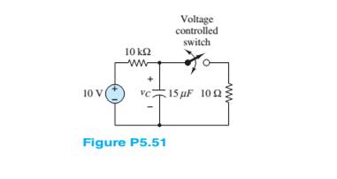
Chapter 5, Problem 5.51HP
The circuit in Figure P5.51 includes a voltage-controlled switch. The switch closes or opens when the voltage across the capacitor reaches the value
Expert Solution & Answer
Want to see the full answer?
Check out a sample textbook solution
Students have asked these similar questions
A capacitor "C", an inductor "L" and a switch "S" are connected in series. When the switch is open, the plate to the left of the capacitor has charge "Qo". The switch is closed the load and current vary sinusoidally with time. Represent graphically the load "Qo" and the intensity of current "I" as a function of time "t", and explain why the current leads the load by a phase difference of 90°.
Describe the behavior of the voltage across the resistor with time as thecapacitor charges. Explain the reason for this behavior.
For the circuit below assuming an ideal switch, preform transient analysis to predict the voltage
across resistor, R2 and plot the results. The inductor will have zero current as initial condition.
L1
0.005
2
U1
100mH
R1
1k
V1
20Vdc
R2
100
Chapter 5 Solutions
Principles and Applications of Electrical Engineering
Ch. 5 - Write the differential equations fort t0 for iL...Ch. 5 - Write the differential equation fort t0 for vc in...Ch. 5 - Write the differential equation fort t0 for iC in...Ch. 5 - Write the differential equation for t0 for iL in...Ch. 5 - Write the differential equation for t0 for vc in...Ch. 5 - Write the differential equations for t0 for iC and...Ch. 5 - Prob. 5.7HPCh. 5 - Write the differential equation for t0 for iC in...Ch. 5 - Write the differential equation for t0 for iL in...Ch. 5 - Write the differential equations for: t0 for iL...
Ch. 5 - Determine the initial and final conditions on iL...Ch. 5 - Determine the initial and final conditions on vc...Ch. 5 - Determine the initial and final conditions on iC...Ch. 5 - Determine the initial and final conditions on iL...Ch. 5 - Determine the initial and final conditions on vc...Ch. 5 - Determine the initial and final conditions on iC...Ch. 5 - Determine the initial and final conditions on vC...Ch. 5 - Prob. 5.18HPCh. 5 - Prob. 5.19HPCh. 5 - Determine the initial and final conditions on iL...Ch. 5 - At t=0 , just before the switch is opened, the...Ch. 5 - Prob. 5.22HPCh. 5 - Determine the current ic through the capacitor...Ch. 5 - Prob. 5.24HPCh. 5 - Prob. 5.25HPCh. 5 - Assume that steady-state conditions exist in...Ch. 5 - Assume that steady-state conditions exist in the...Ch. 5 - Prob. 5.28HPCh. 5 - Assume that steady-state conditions exist in the...Ch. 5 - Find the Thévenin equivalent network seen by the...Ch. 5 - Prob. 5.31HPCh. 5 - Prob. 5.32HPCh. 5 - Prob. 5.33HPCh. 5 - For t0 , the circuit shown in Figure P5.34 is at...Ch. 5 - The circuit in Figure P5.35 is a simple model of...Ch. 5 - Prob. 5.36HPCh. 5 - Determine the current iC through the capacitor in...Ch. 5 - Determine the voltage vL across the inductor in...Ch. 5 - Prob. 5.39HPCh. 5 - For t0 , the circuit shown in Figure P5.39 is at...Ch. 5 - Prob. 5.41HPCh. 5 - Prob. 5.42HPCh. 5 - Prob. 5.43HPCh. 5 - Prob. 5.44HPCh. 5 - For the circuit shown in Figure P5.41, assume that...Ch. 5 - Prob. 5.46HPCh. 5 - Prob. 5.47HPCh. 5 - For the circuit in Figure P5.47, assume...Ch. 5 - In the circuit in Figure P5.49, how long after the...Ch. 5 - Refer to Figure P5.49 and assume that the switch...Ch. 5 - The circuit in Figure P5.51 includes a...Ch. 5 - At t=0 the switch in the circuit in Figure...Ch. 5 - Prob. 5.53HPCh. 5 - The analogy between electrical and thermal systems...Ch. 5 - The burner and pot of Problem 5.54 can be modeled...Ch. 5 - Prob. 5.56HPCh. 5 - Prob. 5.57HPCh. 5 - Prob. 5.58HPCh. 5 - The circuit in Figure P5.59 models the charging...Ch. 5 - Prob. 5.60HPCh. 5 - In the circuit shown in Figure P5.61:...Ch. 5 - Prob. 5.62HPCh. 5 - If the switch shown in Figure P5.63 is closed at...Ch. 5 - Prob. 5.64HPCh. 5 - Prob. 5.65HPCh. 5 - Prob. 5.66HPCh. 5 - Prob. 5.67HPCh. 5 - Prob. 5.68HPCh. 5 - Assume the switch in the circuit in Figure...Ch. 5 - Prob. 5.70HPCh. 5 - Prob. 5.71HPCh. 5 - Prob. 5.72HPCh. 5 - Prob. 5.73HPCh. 5 - Prob. 5.74HPCh. 5 - Prob. 5.75HPCh. 5 - Prob. 5.76HPCh. 5 - Prob. 5.77HPCh. 5 - Prob. 5.78HPCh. 5 - Prob. 5.79HPCh. 5 - Assume the circuit in Figure P5.80 is in DC steady...Ch. 5 - Prob. 5.81HPCh. 5 - For t0 , determine v in Figure P5.82, assuming DC...
Knowledge Booster


Learn more about
Need a deep-dive on the concept behind this application? Look no further. Learn more about this topic, electrical-engineering and related others by exploring similar questions and additional content below.Similar questions
- A capacitor has a reactance of 40 when operated on a 50 Hz supply. Determine the value of its capacitance. In a series R–L circuit the p.d. across the resistance R is 12V and the p.d. across the inductance L is 5V. Find the supply voltage and the phase angle between current and voltagearrow_forwardlow voltage systems What is the general reason for selecting the capacitor voltage with a value greater than 400 V (such as 415,445 V) in Reactive Power Compensation? a) Reduce losses b) Harmonics C)Current decrease d) Voltage droparrow_forwarda) The voltage across a 20uF capacitance is v. = 50 sin( at - 80) volts and Frequency equal to 100 Hz. Determine the current through the capacitor i and sketch its waveform. b) Define phasorarrow_forward
- 1)The value of the capacitance reactive power in VAR is? /2) The value of the capacitor in micro farad is?arrow_forwardA resistor & a capacitor are connected in series across 230V, ac supply. The current taken by the circuit is 4 A for 50 Hz frequency. The current is reduced to 2 A, when the frequency of supply is decreased to 40 Hz. Determine the value of resistor & the capacitor.arrow_forwardA 20-ohm resistor and a capacitor are connected in series with a battery of 60 volts. At t = 0, there is no charge on the capacitor. Find the capacitance if the current at t = 5 seconds is 3/e^s amperes. Ans. 0.05 Faradsarrow_forward
- a. Show how you would connect all five capacitors to get a maximum capacitance and find the maximum capacitance in terms of C. b. Show how you would connect all five capacitors to get a minimum capacitance and find the minimum capacitance in terms of C.arrow_forwardA capacitor can be used .............................................. in electrical circuits. Which of the followings fit? To regulate the currents To regulate the voltages To store energy by deposition of electric charges To provide energy as passive circuit element To store energy in the form of magnetic field To create time varying voltages and currents To dissipate energy To convert elektrik energy into heat or lightarrow_forwardPlease explain this question properly A capacitor has a reactance of 40 when operated on a 50 Hz supply. Determine the value of its capacitance. In a series R–L circuit the p.d. across the resistance R is 12V and the p.d. across the inductance L is 5V. Find the supply voltage and the phase angle between current and voltagearrow_forward
- (iii). Determine the net capacitance C of the capacitor network shown in figure. Assume C-3 pF, C2 5 pF, C 6 pF and C 9 pl. Determine the charge on each capacitor, assun there is a potential difference of 15 V across cach network. C2 C, C3arrow_forwardhow do i calculate the inverse capacitance and its uncertainty if the capacitance value 1.8748+/- 0.0006. please show steps im using this example to do my other values.arrow_forward3-10 A0.25-F capacitor has a current waveform i(t) as shown in Figure P3–10. Determine and plot the voltage waveform v(t) as a function of time. The capacitor is initially a and plot the voltage waveform v(t) as a function of time. The capacitor is imu uncharged. FIGURE P3-10 ilt) 4 A 6. -4 Aarrow_forward
arrow_back_ios
SEE MORE QUESTIONS
arrow_forward_ios
Recommended textbooks for you
 Introductory Circuit Analysis (13th Edition)Electrical EngineeringISBN:9780133923605Author:Robert L. BoylestadPublisher:PEARSON
 Delmar's Standard Textbook Of ElectricityElectrical EngineeringISBN:9781337900348Author:Stephen L. HermanPublisher:Cengage Learning
 Programmable Logic ControllersElectrical EngineeringISBN:9780073373843Author:Frank D. PetruzellaPublisher:McGraw-Hill Education
 Fundamentals of Electric CircuitsElectrical EngineeringISBN:9780078028229Author:Charles K Alexander, Matthew SadikuPublisher:McGraw-Hill Education
 Electric Circuits. (11th Edition)Electrical EngineeringISBN:9780134746968Author:James W. Nilsson, Susan RiedelPublisher:PEARSON
 Engineering ElectromagneticsElectrical EngineeringISBN:9780078028151Author:Hayt, William H. (william Hart), Jr, BUCK, John A.Publisher:Mcgraw-hill Education,
Introductory Circuit Analysis (13th Edition)
Electrical Engineering
ISBN:9780133923605
Author:Robert L. Boylestad
Publisher:PEARSON
Delmar's Standard Textbook Of Electricity
Electrical Engineering
ISBN:9781337900348
Author:Stephen L. Herman
Publisher:Cengage Learning
Programmable Logic Controllers
Electrical Engineering
ISBN:9780073373843
Author:Frank D. Petruzella
Publisher:McGraw-Hill Education
Fundamentals of Electric Circuits
Electrical Engineering
ISBN:9780078028229
Author:Charles K Alexander, Matthew Sadiku
Publisher:McGraw-Hill Education
Electric Circuits. (11th Edition)
Electrical Engineering
ISBN:9780134746968
Author:James W. Nilsson, Susan Riedel
Publisher:PEARSON
Engineering Electromagnetics
Electrical Engineering
ISBN:9780078028151
Author:Hayt, William H. (william Hart), Jr, BUCK, John A.
Publisher:Mcgraw-hill Education,
Nodal Analysis for Circuits Explained; Author: Engineer4Free;https://www.youtube.com/watch?v=f-sbANgw4fo;License: Standard Youtube License