
Videos
Assume that steady-state conditions exist in the circuit shown in Figure P5.27 for
Want to see the full answer?
Check out a sample textbook solution
Chapter 5 Solutions
Principles and Applications of Electrical Engineering


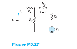
- 7 Steady-state conditions exist in the circuit shown in Figure P5.27 at t < 0. The switch is closed at t = 0. V = 12 V R = 0.68 k2 R = 2.2 k2 R = 1.8 k2 C= 0.47 µF Determine the current through the capacitor at t = 0+, just after the switch is closed. ww. idt) R. t= 0 R1 Ry ww-arrow_forward4 If the switch in the circuit shown in Figure P5.64 is closed at t = 0 and Vs = 12 V C = 130 µF R = 2.3 k2 R, = 7 k2 L= 30 mH determine the current through the inductor and the voltage across the capacitor and across Rị after the circuit has returned to a steady state. t= 0 R1 Vs R2arrow_forwardGiven circuit below, use superposition to find voltage across the capacitor, vclt). Frequency is 100 Hz. 6kn 4kn reee zkn O SmA <45 Vc (t) DC a) Given circuit below and switch ciosed for long time, what is the value of Vc? 5mA 3 luk bị At0, switch is opened. Write a mathematical expression for Velt) after opening of the switch. Evaluate this voltage at te10 ms. Attach File Browse Local Fies rowie Conent Cotection 74°Farrow_forward
- 8 For t > 0, the circuit shown in Figure P5.22 is at steady state. The switch is changed as shown at t = 0. Vsi = 35 V C = 11 µF Vsz = 130 V R = 17 k2 R = 7 k2 R = 23 k2 Determine the time constant of the circuit for t> 0.arrow_forward1 Just before the switch is opened at t = 0 in Figure P5.21, the current through the inductor is 1.70 mA in the direction shown. Vs = 12 V L = 0.9 mH R = 6 k2 R2 = 6 k2 R = 3 k2 Determine the time constant of the circuit for t > 0.arrow_forward1. What impedance vector 0 – j22 represents:A. A pure resistance.B. A pure inductance.C. A pure capacitance.D. An inductance combined with a resistance.arrow_forward
- Support that there. Icincuit Esithu an reasistanee on the and capacitance of /4 F. The EMF is ) 4 Cos 2t , The initial is an RC Cnerat current. The alternating cincuit is '/ 2 L Elt) the cincuit is qu(0) = 1V. Find the charge on the cincuit after t seconds. charge onarrow_forward9 At t 0.arrow_forward6 At t< 0, the circuit shown in Figure P5.66 is at steady state, and the voltage across the capacitor is +7 V. The switch is changed as shown at t= 0, and Vs = 12 V C= 3,300 µF R = 9.1 k2 R = 4.3 k2 R3 = 4.3 k2 L= 16 mH Determine the initial voltage across R2 just after the switch is changed. t=0 Le )V½ R R 2 R3 ww-arrow_forward
- A capacitor "C", an inductor "L" and a switch "S" are connected in series. When the switch is open, the plate to the left of the capacitor has charge "Qo". The switch is closed the load and current vary sinusoidally with time. Represent graphically the load "Qo" and the intensity of current "I" as a function of time "t", and explain why the current leads the load by a phase difference of 90°.arrow_forward2 At t < 0, the circuit shown in Figure P5.22 is at steady state. The switch is changed as shown at t = 0. Vsi = 35 V C = 11 µF Vsz = 130 V R = 17 k2 R2 = 7 k2 R = 23 k2 Determine at t = 0+ the initial current through R just after the switch is changed. 1= 0 R3 Vs1 Vs2arrow_forward5. RC Charging Circuit is shown in the figure. Find the differantial equation and its solution of represent the charcing circuit using KIRCHHOFF's RULE by meaning changing the t- 0 R= 47kn charges with respect to time. (Vc =%, 1 = ) and then Calculate: dt a. q(t = 100) =? The charge across the Capacitor after 100 seconds b. Vc(t = 100) =?The voltage across the Capacitor after 100 seconds E=5V Vc C- 1000uF l1=10 Aarrow_forward
 Introductory Circuit Analysis (13th Edition)Electrical EngineeringISBN:9780133923605Author:Robert L. BoylestadPublisher:PEARSON
 Delmar's Standard Textbook Of ElectricityElectrical EngineeringISBN:9781337900348Author:Stephen L. HermanPublisher:Cengage Learning
 Programmable Logic ControllersElectrical EngineeringISBN:9780073373843Author:Frank D. PetruzellaPublisher:McGraw-Hill Education
 Fundamentals of Electric CircuitsElectrical EngineeringISBN:9780078028229Author:Charles K Alexander, Matthew SadikuPublisher:McGraw-Hill Education
 Electric Circuits. (11th Edition)Electrical EngineeringISBN:9780134746968Author:James W. Nilsson, Susan RiedelPublisher:PEARSON
 Engineering ElectromagneticsElectrical EngineeringISBN:9780078028151Author:Hayt, William H. (william Hart), Jr, BUCK, John A.Publisher:Mcgraw-hill Education,