
Videos
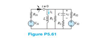
In the circuit shown in Figure P5.61:
Assume that DC steady-state conditions exist for
Want to see the full answer?
Check out a sample textbook solution
Chapter 5 Solutions
Principles and Applications of Electrical Engineering


- %3D Q5/ A. Design ring counter has the initial state Q,02 Q.Qo = 1010arrow_forward. For the circuit shown in figure. The value of Zi is .................. kohm . * 82.86 104.86 84.86 92.86 99.86 108.86 The value of re is ..............ohm. . * 4.718 9.418 5.218 7.918 8.318 6.818 The value of Zi is .................. ohm . NOTE: use with CE in place (bypassed) * 720.67 630.67 650.67 640.67 710.67 680.67 The value of Av is .................. . NOTE: use with CE in place (bypassed) * -382.675 -272.675 -282.675 -362.675 -322.675 -392.675 The value of Av is .................. . * -1.805 -1.205 -1.105 -2.506 -2.405 -2.706 The…arrow_forwardIn an R-L-C series circuit a maximum current of 0.5 A is obtained by varying the value of inductance L. The supply voltage is fixed at 230 V, 50 Hz. When maximum current flows through the circuit, the voltage measured across the capacitor is 350 V. What are the values of the circuit parameters? ..arrow_forward
- NOTE ON SIGN CONVENTIONS: The open-circuit voltage Voc is the open-circuit value of Vab. The short-circuit current is the current which flows from a to b in a wire connected between these two terminals. Please use these conventions throughout this assignment. Problem 5-1. For the network of figure P5-1, determine the Thevenin equivalent with respect to the terminals a and b. 20V + 1ΚΩ 10mA 2ΚΩ ww 8ΚΩ ww 4ΚΩ. 1.5ΚΩ a barrow_forwardFind IA, IB, IC, V1kohms, V5.1kohms, and V2kohmsarrow_forwardQ3) Draw the output waveform for the circuit in figure below. Assume that +Vout(max) = +10 V and - Vout(max) = -10V. ZD1 ZD2 Vin 5 R1 ww Vout 1kQ -5 0 3.3V + U1 2.2Varrow_forward
- 1)The value of the capacitance reactive power in VAR is? /2) The value of the capacitor in micro farad is?arrow_forwardQ3) Draw the output waveform for the circuit in figure below. Assume that +Vout(max) = +10 V and - Vout(max) = -10V. ZD1 ZD2 Vin R1 5 Vout 1kQ -5 0 3.3V U1 + 2.2Varrow_forward3-2) Draw the circuit diagram to output F given in the expression above by referring to schematics for 2-2) and 2-3). Use the space below to draw both the IC with pin assignments and a circuit F schematic. Schematic diagram: IC diagram: +3V IND Cate che GNDarrow_forward
- In circuit shown in figure, the operating point is chosen such that = 9V and ß = 49 Ic 1.75mA, VCE = 3.1V,If Rc = 2.7KN, Vcc %3| Determine the values of R1, R2 and Rg [VBe = 0.3V and I = 10ß] RC R1 = Vcc RE R2 www www www wwwarrow_forwardQ/ Design a circuit to limit a 20 V rms sinusoidal voltage to a maximum positive amplitude of 10 V and a maximum negative amplitude of -5 V using a single 14 V dc voltage sour.arrow_forwardQ5. Draw the circuit diagram to implement the expression A BC(AB + Ā B)arrow_forward
 Introductory Circuit Analysis (13th Edition)Electrical EngineeringISBN:9780133923605Author:Robert L. BoylestadPublisher:PEARSON
 Delmar's Standard Textbook Of ElectricityElectrical EngineeringISBN:9781337900348Author:Stephen L. HermanPublisher:Cengage Learning
 Programmable Logic ControllersElectrical EngineeringISBN:9780073373843Author:Frank D. PetruzellaPublisher:McGraw-Hill Education
 Fundamentals of Electric CircuitsElectrical EngineeringISBN:9780078028229Author:Charles K Alexander, Matthew SadikuPublisher:McGraw-Hill Education
 Electric Circuits. (11th Edition)Electrical EngineeringISBN:9780134746968Author:James W. Nilsson, Susan RiedelPublisher:PEARSON
 Engineering ElectromagneticsElectrical EngineeringISBN:9780078028151Author:Hayt, William H. (william Hart), Jr, BUCK, John A.Publisher:Mcgraw-hill Education,