
Videos
Determine the current
Want to see the full answer?
Check out a sample textbook solution
Chapter 5 Solutions
Principles and Applications of Electrical Engineering


- For t > 0, determine for what value of t v = 7.5 Vin the circuit of Figure P5.79 if the circuit is in steadystate at t = 0−.arrow_forwardSolve for the node voltages shown in Figure P5.53. 10/0 (+ 10 2 +j20 2 15 n 1 Figure P5.53 000arrow_forward2 Determine vc(t) for t > 0. The voltage across the capacitor in Figure P5.32 just before the switch is changed is given below. vc(0-) = -7 V I, = 17 mA C = 0.55 µF R = 7 k2 R2 = 3.3 k2 t= 0 R2 R1 CVct)arrow_forward
- 3 Assume that the circuit shown in Figure P5.73 is underdamped and that the circuit initially has no energy stored. It has been observed that after the switch is closed at t = 0, the capacitor voltage reaches an initial peak value of 70 V when t = 57/3 µs and a second peak value of 53.2 V when t = 57 us, and it eventually approaches a steady-state value of 50 V. If C = 1.6 nF, what are the values of Rand L? t= 0 wwarrow_forwardRs Vs R2: Figure P5.47 8 For the circuit of Figure P5.47, assume Vs 100 V, Rs = 4 k2, R¡ = 2 k2, R2 = R3 = 6 k2, C = 1 µF, and the circuit is in a steady-state condition before the switch opens. Find the value of vc 2.666 ms after the switch opens. %24arrow_forwardAt 0-, no currrent flows through the capacitors because they are open, how did you combine the capacitors for the voltage divider since it is the capacitance value and not reactance, is it right? Can we just combine the capacitance value? Please explain. I did not understand..arrow_forward
- t=0 Rs1 Rs2 LE R Vsi R2 Vs2 Figure P5.61 2 In the circuit shown in Figure P5.61 Vsi = 12 V Rsi = 50 2 Vsz = 12 V Rsz = 50 2 R = 2.2 k2 R2 = 600 2 L = 7.8 mH C = 68 µF Assume that DC steady-state conditions exist at t < 0. Determine the voltage across the capacitor and thearrow_forward1. What impedance vector 0 – j22 represents:A. A pure resistance.B. A pure inductance.C. A pure capacitance.D. An inductance combined with a resistance.arrow_forwardGiven circuit below, use superposition to find voltage across the capacitor, vclt). Frequency is 100 Hz. 6kn 4kn reee zkn O SmA <45 Vc (t) DC a) Given circuit below and switch ciosed for long time, what is the value of Vc? 5mA 3 luk bị At0, switch is opened. Write a mathematical expression for Velt) after opening of the switch. Evaluate this voltage at te10 ms. Attach File Browse Local Fies rowie Conent Cotection 74°Farrow_forward
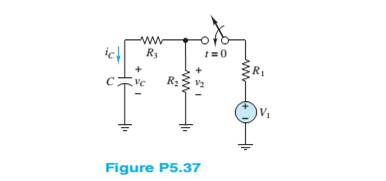
- 7 Steady-state conditions exist in the circuit shown in Figure P5.27 at t < 0. The switch is closed at t = 0. V = 12 V R = 0.68 k2 R = 2.2 k2 R = 1.8 k2 C= 0.47 µF Determine the current through the capacitor at t = 0+, just after the switch is closed. ww. idt) R. t= 0 R1 Ry ww-arrow_forwardQ5. For an exhibition project you are designing a circuit of signal processor which can be connected to 230V, 50 Hz supply have a 5.0 H inductor, 80 μ F capacitor and 40Ω resistor kept in series. How can you evaluate the rms current and average power delivered to the circuit? Based on your observation, evaluate the potential drop across capacitance and inductor. Comment about that r m s voltage found in this circuit is less than peak voltage? Justify it with your answer. If you remove the inductor and connect a bulb in series with a capacitor. What will happen to the brightness of bulb if it is connected to DC source and then to an AC source. Assess and find reason for your observations in each case.arrow_forward5. RC Charging Circuit is shown in the figure. Find the differantial equation and its solution of represent the charcing circuit using KIRCHHOFF's RULE by meaning changing the t- 0 R= 47kn charges with respect to time. (Vc =%, 1 = ) and then Calculate: dt a. q(t = 100) =? The charge across the Capacitor after 100 seconds b. Vc(t = 100) =?The voltage across the Capacitor after 100 seconds E=5V Vc C- 1000uF l1=10 Aarrow_forward
 Introductory Circuit Analysis (13th Edition)Electrical EngineeringISBN:9780133923605Author:Robert L. BoylestadPublisher:PEARSON
 Delmar's Standard Textbook Of ElectricityElectrical EngineeringISBN:9781337900348Author:Stephen L. HermanPublisher:Cengage Learning
 Programmable Logic ControllersElectrical EngineeringISBN:9780073373843Author:Frank D. PetruzellaPublisher:McGraw-Hill Education
 Fundamentals of Electric CircuitsElectrical EngineeringISBN:9780078028229Author:Charles K Alexander, Matthew SadikuPublisher:McGraw-Hill Education
 Electric Circuits. (11th Edition)Electrical EngineeringISBN:9780134746968Author:James W. Nilsson, Susan RiedelPublisher:PEARSON
 Engineering ElectromagneticsElectrical EngineeringISBN:9780078028151Author:Hayt, William H. (william Hart), Jr, BUCK, John A.Publisher:Mcgraw-hill Education,