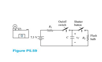
The circuit in Figure P5.59 models the charging circuit of an electronic camera hash. The flash should be charged to
a. How long does it take the flash to recharge after taking a picture?
b. The shutter button stays closed for 1/30 s. How much energy is delivered to the flash bulb
c. If the shutter button is pressed 3 s after a flash, how much energy is delivered to the bulb

Want to see the full answer?
Check out a sample textbook solution
Chapter 5 Solutions
Principles and Applications of Electrical Engineering
- 1. A certain full-wave rectifier has a peak output voltage of 30V. A 50 mF capacitor filter is connected to the rectifier. Calculate the RMS ripple developed across a 600 W load resistance 2. It is a process of allowing electric current to flow only in one direction that is changing A.C in to D.C.arrow_forward· A single-phase controlled rectifier bridge consists of one SCR and three diodes as shown in figure. The average output voltage and power delivered to battery for a firing angle of 45° are R = 52 D3 230V L= 8mH %3D 50 Hz D D2 E= 100V (a) 88.37 V, 1.837 kW (b) 191.88 V, 1.876 kW (c) 100 V, 3.525 kW (d) 88.37 V, 3.525 kWarrow_forwardFull-wave rectified sine wave circuit is used to measure the RMS value of a half square wave with the help of PMMC meter. The meter was actually calibrated for sine wave. The circuit uses a meter movement with a full scale deflection current of 200uA and internal meter resistance of 5kΩ. Assuming Non-ideal diodes having resistance 1kΩ, Analyze the circuit to determine the value of series multiplier resister and the corrected RMS voltage, if meter is to read 225V RMS full-scale.arrow_forward
- Please solve this question quecklyarrow_forwardPlease answer in typing formatarrow_forward5. A voltage source produces a "Triangle" wave and is connected to a series diode and resistor circuit as shown. D1 KH D V1 #1 V R1 R Using the nominal piecewise linear model for a diode, determine from the following possibilities the graph that best represents the voltage across the resistor? (Delete those that do not apply) (Blue curve VR, dashed curve V1). Then determine which graph best represents the voltage across the diode.arrow_forward
- Cyclic Voltammetry and Charge-discharge The given figure is the Galvanostatic Charge-discharge curves of a supercapacitor made with MnO2 coated on a CNT electrode. Potential is measured with respect to time by applying different current densities. Based on the plot, answer the following questions 4. Is it possible to estimate maximum power of the device with this charge-discharge curve? If possible, explain how you would do it. (calculation is not necessary)arrow_forwardrefer to the circuit below, what is the secondary rms voltage, filtered dc voltage, maximum voltage at the output, pk to pk ripple voltage, and pulsating DC voltage of the circuit?arrow_forwardIn the given circuit, (diodes will be considered ideal. a) Draw the V0 output by calculating it according to the input. b) Calculate the average and effective value of the V0 output. c) What are the advantages and disadvantages of using two diodes and two resistors instead of four diodes? Input signal Vm = ± 10V (peak to peak), T = 2π (period), R = 2karrow_forward
 Introductory Circuit Analysis (13th Edition)Electrical EngineeringISBN:9780133923605Author:Robert L. BoylestadPublisher:PEARSON
 Delmar's Standard Textbook Of ElectricityElectrical EngineeringISBN:9781337900348Author:Stephen L. HermanPublisher:Cengage Learning
 Programmable Logic ControllersElectrical EngineeringISBN:9780073373843Author:Frank D. PetruzellaPublisher:McGraw-Hill Education
 Fundamentals of Electric CircuitsElectrical EngineeringISBN:9780078028229Author:Charles K Alexander, Matthew SadikuPublisher:McGraw-Hill Education
 Electric Circuits. (11th Edition)Electrical EngineeringISBN:9780134746968Author:James W. Nilsson, Susan RiedelPublisher:PEARSON
 Engineering ElectromagneticsElectrical EngineeringISBN:9780078028151Author:Hayt, William H. (william Hart), Jr, BUCK, John A.Publisher:Mcgraw-hill Education,


