
Videos
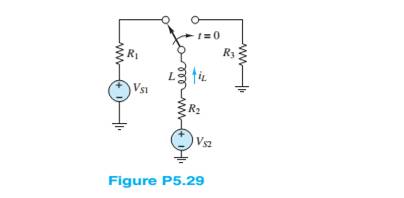
Assume that steady-state conditions exist in the circuit shown in Figure P5.29at
Find the Norton equivalent network seen by the inductor. Use it to determine the time constant of the circuit for
Want to see the full answer?
Check out a sample textbook solution
Chapter 5 Solutions
Principles and Applications of Electrical Engineering


- 6 Determine the voltage across the inductor just before and just after the switch is changed in Figure P5.26. Assume steady-state conditions exist for t < 0. Vs = 12 V R, = 0.7 2 R = 22 k2 L= 100 mH 1=0 R, R1arrow_forward2 Determine vc(t) for t > 0. The voltage across the capacitor in Figure P5.32 just before the switch is changed is given below. vc(0-) = -7 V I, = 17 mA C = 0.55 µF R = 7 k2 R2 = 3.3 k2 t= 0 R2 R1 CVct)arrow_forwardAt 0-, no currrent flows through the capacitors because they are open, how did you combine the capacitors for the voltage divider since it is the capacitance value and not reactance, is it right? Can we just combine the capacitance value? Please explain. I did not understand..arrow_forward
- *P5.53. Solve for the node voltages shown in Figure P5.53. 10 Ω I₁ V₁ +j20 Ω 10/0° + V₂ 1₂ - Figure P5.53 15 Ω 13 es a - - j5 Ωarrow_forwardP5.90. a. Find the Thévento and Norton equivalent circuits for the circuit shown in Figure P5.90. b. Find the maximum power that this circuit can deliver to a load if the load can have any complex impedance. c. Repeat if the load must be purely resistive. 100/45° 10 Ω www enpea gineering Pr +j5 n Figure P5.90 15/0°arrow_forward1 Just before the switch is opened at t = 0, the current through the inductor is 1.70 mA in the direction shown in Figure P5.21. Did steady-state conditions exist just before the switch was opened? L= 0.9 mH Vs = 12 V R = 6 k2 R2 = 6 k2 R = 3 k2 t = 0 R2 R1 L R3{Va3 V83arrow_forward
- 57. The Thévenin equivalent of a two-terminal network is shown in Figure P5.87. The fre- quency is f = 60 Hz. We wish to connect a load across terminals a-b that consists of a resistance and a capacitance in parallel such that the power delivered to the resistance is maximized. Find the value of the resistance and the value of the capacitance. Z, = 10 +j5 Q o a V, = 100/0° V Figure P5.87arrow_forwardGiven circuit below, use superposition to find voltage across the capacitor, vclt). Frequency is 100 Hz. 6kn 4kn reee zkn O SmA <45 Vc (t) DC a) Given circuit below and switch ciosed for long time, what is the value of Vc? 5mA 3 luk bị At0, switch is opened. Write a mathematical expression for Velt) after opening of the switch. Evaluate this voltage at te10 ms. Attach File Browse Local Fies rowie Conent Cotection 74°Farrow_forwardA First and second quadrant chopper is supplied from a 240 V de source. The load consists of a 102 resistance in series with a 20mH inductance. The chopper operates with M-0.7 and at 1.2kHz. Find: a. The quadrant of operation b. Vo,de c. Io,de d. Can the chopper operate in the second quadrant? justify your answer e. The on-time and off-time of the modulating switch f. Output current ripple factor g. The average and RMS current the passes through S1.arrow_forward
- Calculate the steady state currents flowing through inductors L₁ and L₂ and the steady state voltage across capacitor C in the circuit L₁ mm Vs = 20 V L₁ = 4 mH R₁ = 1 A R₂ = 3 L₂= 7 mH C = 6 4F shown below: Ri wwwww HH Carrow_forwardThe capacitor has been added to the load in the circuit shown in figure below to maximize the power absorbed by the 4000-V resistor. What value of capacitance should be used to accomplish that objective?arrow_forward2 At t < 0, the circuit shown in Figure P5.22 is at steady state. The switch is changed as shown at t = 0. Vsi = 35 V C = 11 µF Vsz = 130 V R = 17 k2 R2 = 7 k2 R = 23 k2 Determine at t = 0+ the initial current through R just after the switch is changed. 1= 0 R3 Vs1 Vs2arrow_forward
 Introductory Circuit Analysis (13th Edition)Electrical EngineeringISBN:9780133923605Author:Robert L. BoylestadPublisher:PEARSON
 Delmar's Standard Textbook Of ElectricityElectrical EngineeringISBN:9781337900348Author:Stephen L. HermanPublisher:Cengage Learning
 Programmable Logic ControllersElectrical EngineeringISBN:9780073373843Author:Frank D. PetruzellaPublisher:McGraw-Hill Education
 Fundamentals of Electric CircuitsElectrical EngineeringISBN:9780078028229Author:Charles K Alexander, Matthew SadikuPublisher:McGraw-Hill Education
 Electric Circuits. (11th Edition)Electrical EngineeringISBN:9780134746968Author:James W. Nilsson, Susan RiedelPublisher:PEARSON
 Engineering ElectromagneticsElectrical EngineeringISBN:9780078028151Author:Hayt, William H. (william Hart), Jr, BUCK, John A.Publisher:Mcgraw-hill Education,