
Principles and Applications of Electrical Engineering
6th Edition
ISBN: 9780073529592
Author: Giorgio Rizzoni Professor of Mechanical Engineering, James A. Kearns Dr.
Publisher: McGraw-Hill Education
expand_more
expand_more
format_list_bulleted
Videos
Textbook Question
Chapter 5, Problem 5.50HP
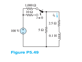
Refer to Figure P5.49 and assume that the switch takes 5 ms to move from one contact to the other. Also assume that during this Lime neither switch position has electrical contact. Find:
a.
b. The maximum voltage between the contacts during the 5-ms duration of the switching.
Hint: This problem requires solving both a turnoff and a turn-on transient problem.
Expert Solution & Answer
Want to see the full answer?
Check out a sample textbook solution
Students have asked these similar questions
In the circuit of figure Nº A, the secondary voltage Vs is 15 volts rms with a frequency of 60 Hz, R equal to 100 Ohms and C equal to 1000 microfarads. The diodes are silicon (Vd = 0.7 volts) and the Zener diode is 15 volts. Determine:a) The magnitude of the ripple voltage at Cb) The Magnitude of the Peak Inverse Voltage (PIV) for D1 and D2..
In the circuit of the following figure, the input voltage Vs is 15 volts rms with a frequency of 60 Hz, R equals 150 Ohms and C equals 100,000 Pico Farads. The diodes are Germanium (Vd = 0.2 volts) and the Zener diode is 12 volts.
a) The magnitude of the ripple voltage at Cb) The Magnitude of the Peak Inverse Voltage (PIV) for D1 and D2.
(c)
A buck converter, as shown in Figure Q3(i) below, is working in steady
state. The output voltage and the inductor current can be assumed to
be ripple free. Figure Q3(ii) shows the inductor voltage VL during a
complete switching interval. Assuming all devices are ideal, determine
(i)
The output voltage, input voltage and the duty cycle of the buck
converter.
(ii)
The inductor value required to maintain a peak-to-peak ripple
current of 0.4A, if the switching frequency is 100kHz.
V.
M
30V
本D
c+ v.
TON
TOFF
20V
Ts
(i)
(ii)
Figure Q3.
(i) Equivalent circuit of a buck converter and (ii) inductor voltage
over one complete cycle.
Chapter 5 Solutions
Principles and Applications of Electrical Engineering
Ch. 5 - Write the differential equations fort t0 for iL...Ch. 5 - Write the differential equation fort t0 for vc in...Ch. 5 - Write the differential equation fort t0 for iC in...Ch. 5 - Write the differential equation for t0 for iL in...Ch. 5 - Write the differential equation for t0 for vc in...Ch. 5 - Write the differential equations for t0 for iC and...Ch. 5 - Prob. 5.7HPCh. 5 - Write the differential equation for t0 for iC in...Ch. 5 - Write the differential equation for t0 for iL in...Ch. 5 - Write the differential equations for: t0 for iL...
Ch. 5 - Determine the initial and final conditions on iL...Ch. 5 - Determine the initial and final conditions on vc...Ch. 5 - Determine the initial and final conditions on iC...Ch. 5 - Determine the initial and final conditions on iL...Ch. 5 - Determine the initial and final conditions on vc...Ch. 5 - Determine the initial and final conditions on iC...Ch. 5 - Determine the initial and final conditions on vC...Ch. 5 - Prob. 5.18HPCh. 5 - Prob. 5.19HPCh. 5 - Determine the initial and final conditions on iL...Ch. 5 - At t=0 , just before the switch is opened, the...Ch. 5 - Prob. 5.22HPCh. 5 - Determine the current ic through the capacitor...Ch. 5 - Prob. 5.24HPCh. 5 - Prob. 5.25HPCh. 5 - Assume that steady-state conditions exist in...Ch. 5 - Assume that steady-state conditions exist in the...Ch. 5 - Prob. 5.28HPCh. 5 - Assume that steady-state conditions exist in the...Ch. 5 - Find the Thévenin equivalent network seen by the...Ch. 5 - Prob. 5.31HPCh. 5 - Prob. 5.32HPCh. 5 - Prob. 5.33HPCh. 5 - For t0 , the circuit shown in Figure P5.34 is at...Ch. 5 - The circuit in Figure P5.35 is a simple model of...Ch. 5 - Prob. 5.36HPCh. 5 - Determine the current iC through the capacitor in...Ch. 5 - Determine the voltage vL across the inductor in...Ch. 5 - Prob. 5.39HPCh. 5 - For t0 , the circuit shown in Figure P5.39 is at...Ch. 5 - Prob. 5.41HPCh. 5 - Prob. 5.42HPCh. 5 - Prob. 5.43HPCh. 5 - Prob. 5.44HPCh. 5 - For the circuit shown in Figure P5.41, assume that...Ch. 5 - Prob. 5.46HPCh. 5 - Prob. 5.47HPCh. 5 - For the circuit in Figure P5.47, assume...Ch. 5 - In the circuit in Figure P5.49, how long after the...Ch. 5 - Refer to Figure P5.49 and assume that the switch...Ch. 5 - The circuit in Figure P5.51 includes a...Ch. 5 - At t=0 the switch in the circuit in Figure...Ch. 5 - Prob. 5.53HPCh. 5 - The analogy between electrical and thermal systems...Ch. 5 - The burner and pot of Problem 5.54 can be modeled...Ch. 5 - Prob. 5.56HPCh. 5 - Prob. 5.57HPCh. 5 - Prob. 5.58HPCh. 5 - The circuit in Figure P5.59 models the charging...Ch. 5 - Prob. 5.60HPCh. 5 - In the circuit shown in Figure P5.61:...Ch. 5 - Prob. 5.62HPCh. 5 - If the switch shown in Figure P5.63 is closed at...Ch. 5 - Prob. 5.64HPCh. 5 - Prob. 5.65HPCh. 5 - Prob. 5.66HPCh. 5 - Prob. 5.67HPCh. 5 - Prob. 5.68HPCh. 5 - Assume the switch in the circuit in Figure...Ch. 5 - Prob. 5.70HPCh. 5 - Prob. 5.71HPCh. 5 - Prob. 5.72HPCh. 5 - Prob. 5.73HPCh. 5 - Prob. 5.74HPCh. 5 - Prob. 5.75HPCh. 5 - Prob. 5.76HPCh. 5 - Prob. 5.77HPCh. 5 - Prob. 5.78HPCh. 5 - Prob. 5.79HPCh. 5 - Assume the circuit in Figure P5.80 is in DC steady...Ch. 5 - Prob. 5.81HPCh. 5 - For t0 , determine v in Figure P5.82, assuming DC...
Knowledge Booster


Learn more about
Need a deep-dive on the concept behind this application? Look no further. Learn more about this topic, electrical-engineering and related others by exploring similar questions and additional content below.Similar questions
- Explain five (5) applications of the hall effects With the aid of a diagram, explain how a P-N Junction is form. State five (5) application of PN Junction, and explain the property of the PN junction that make those application possible. Explain what carrier mobility is and elaborate on the factors that influence carrier mobility. A 80 V rms is stepped down to 18V rms by a transformer. The output from the transformer is a. rectified using a half wave rectifier circuit and connected to a 47.5 Q load resistor. Draw a circuit diagram of this arrangement and the waveform at each stage.arrow_forwardQ5. For the following center tapped transformer, show the waveform across each half of the secondary winding and across Ri, when a 100 V peak sine wave is applied to the primarywinding. What is the PIV rating must the diode have? (Use constant voltage drop model for the Silicon diode) IN4001 Ry OV 10k) D IN4001arrow_forwardExplain five (5) applications of the hall effects With the aid of a diagram, explain how a P-N Junction is form. iii. State five (5) application of PN Junction, and explain the property of the PN junction that make those application possible. Explain what carrier mobility is and elaborate on the factors that influence carrier mobility. A 80 V rms is stepped down to 18V rms by a transformer. The output from the transformer is rectified using a half wave rectifier circuit and connected to a 47.5 Ω load resistor. Draw a circuit diagram of this arrangement and the waveform at each stage. Calculate the following about the circuit in Figure 2.1 (If silicon diodes are employed in the rectification); the peak value of the output voltage considering the drop across each diode, the average voltage, iii. The current through the load resistor, The current diode, The frequency of the output signal, Calculate the efficiency of the full wave rectifier expressed in percentage. vii. Sketch…arrow_forward
- (P-01) Diode Series (Course: Electronic Devices and Circuit Theory). -Use Equation Operators or write it down on paper/digital paper. -Redraw and Apply. -Please answer without abbreviation. Thank you.arrow_forwardWhat are DC transients? What is the source of transient in electrical circuit / system? How to mitigate transient current? and Transient voltage ? Provide 3 sample calculations involving DC circuit under transient current condition on series R-L and Series R-C circuit? Need a simple explanation, can't quite understand the definitions I have currently.arrow_forwardQ1)Fill in the following blanks : 1.lonization coefficients a .y are functions of ....... 2.Time lag for breakdown is ...... 3.Streamer mechanism of breakdown explains the phenomena of electrical breakdown of ....... 4.Paschen's law states that ....... 5. Minimum sparking potential of air is about ....... 6.At standard temperature and pressure the electric field at which breakdown occur in air with a small gap d (cm) is given by .....arrow_forward
- Q5. For the following center tapped transformer, show the wave form across each half of the secondary winding and across R1, when a 100 V peak sine wave is applied to the primarywinding. What is the PIV rating must the diode have? (Use constant voltage drop model for the Silicon diode) IN4001 R 10 ΚΩ I14001 Q6. Can we operate normal PN junction diode in breakdown region for longer duration? Give reason Q7. What is the specialty of Zener diode so as we can operate it in breakdown region for longer duration? Q8. What is the difference between Zener breakdown and Avalanche breakdown? Q9. Draw Zener regulator circuit to obtain regulated DC voltage 6.8 V. Considering input DC voltage in the range from 10V to 30V. Consider load resistance of 10KS. Q10. Determine maximum and minimum value of Zener current if value of series resistance is 1 K, load resistance is 2KN and input varies from 10V to 30V. Zener voltage is 5 V. Q11. What is LED? Q12. Which materials are used in manufacturing of LEDS?…arrow_forwardDescribing the concept of discontinuous conduction mode in power converters, how does continuous conduction mode differ?Make a DC-DC converter circuit that operates in discontinuous conduction mode.arrow_forwardProvide 3 sample calculations involving DC circuit under transient current condition on series R-L and Series R-C circuit? Need a simple supplementary explanation, can't quite understand the definitions I have currently.arrow_forward
- advantages and disadvantages of or effect improvement of transient stability by using waveform relaxation method? I need them in pointsarrow_forwardA single phase – half wave controlled rectifier with freewheeling diode is supplying a load consistingseries connected a resistor and an inductance from a 70.7V (RMS), 50Hz sinusoidal AC source.The firing delay of the thyristor is 90° and the load values are R=10Ω, L=0.1 H. Define the loadcurrent expression and draw the load current by calculating for first two periods. And calculate theaverage values of the load voltage and current.arrow_forwardplease explain in detail how to arrive at these answers. I am not the best at using Kirchoff voltage law.arrow_forward
arrow_back_ios
SEE MORE QUESTIONS
arrow_forward_ios
Recommended textbooks for you
 Introductory Circuit Analysis (13th Edition)Electrical EngineeringISBN:9780133923605Author:Robert L. BoylestadPublisher:PEARSON
 Delmar's Standard Textbook Of ElectricityElectrical EngineeringISBN:9781337900348Author:Stephen L. HermanPublisher:Cengage Learning
 Programmable Logic ControllersElectrical EngineeringISBN:9780073373843Author:Frank D. PetruzellaPublisher:McGraw-Hill Education
 Fundamentals of Electric CircuitsElectrical EngineeringISBN:9780078028229Author:Charles K Alexander, Matthew SadikuPublisher:McGraw-Hill Education
 Electric Circuits. (11th Edition)Electrical EngineeringISBN:9780134746968Author:James W. Nilsson, Susan RiedelPublisher:PEARSON
 Engineering ElectromagneticsElectrical EngineeringISBN:9780078028151Author:Hayt, William H. (william Hart), Jr, BUCK, John A.Publisher:Mcgraw-hill Education,
Introductory Circuit Analysis (13th Edition)
Electrical Engineering
ISBN:9780133923605
Author:Robert L. Boylestad
Publisher:PEARSON
Delmar's Standard Textbook Of Electricity
Electrical Engineering
ISBN:9781337900348
Author:Stephen L. Herman
Publisher:Cengage Learning
Programmable Logic Controllers
Electrical Engineering
ISBN:9780073373843
Author:Frank D. Petruzella
Publisher:McGraw-Hill Education
Fundamentals of Electric Circuits
Electrical Engineering
ISBN:9780078028229
Author:Charles K Alexander, Matthew Sadiku
Publisher:McGraw-Hill Education
Electric Circuits. (11th Edition)
Electrical Engineering
ISBN:9780134746968
Author:James W. Nilsson, Susan Riedel
Publisher:PEARSON
Engineering Electromagnetics
Electrical Engineering
ISBN:9780078028151
Author:Hayt, William H. (william Hart), Jr, BUCK, John A.
Publisher:Mcgraw-hill Education,
Lesson 2 - Source Transformations, Part 2 (Engineering Circuits); Author: Math and Science;https://www.youtube.com/watch?v=7gno74RhVGQ;License: Standard Youtube License