
Videos
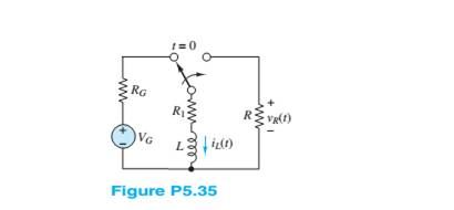
The circuit in Figure P5.35 is a simple model of an automotive ignition system. The switch models the “points” that switch electric power to the cylinder when the fuel-air mixture is compressed. R is the resistance across the gap between the electrodes of the spark plug.
Determine the value of L and
Want to see the full answer?
Check out a sample textbook solution
Chapter 5 Solutions
Principles and Applications of Electrical Engineering


- How much voltage is taken by capacitor #4 (c4)? Select one: a. 7.2 volts b. 6.36 volts c. 5.65 volts d. 4.8 voltsarrow_forwardA three-phase rectifier is supplied by a 173.2-V rms line-to-line 60-Hz source. The RL load is a 100 resistor in series with a 15-mH inductor. Determine THD taking Is1 = 1.35arrow_forwardFor the circuit in the figurea) Determine the time constant.b) Write the mathematical expression for IL, VL and VR, after the switch is closed.c) Determine IL, VL for one, three and five time constants.d) Draw the waveforms of IL, VL and VR.arrow_forward
- 1- A). Which of the following could be used as a discharge device in an inductive AC circuit? a) resistor b) diode c) metal oxide varistor d) "a" and "c", not "b" B. What is the purpose of a discharge device used in conjunction with opening a highly inductive circuit? a) to minimize the possibility of damage to the circuits insulation as a result of a high induced voltage b) to minimize the possibility of endangering the life of the person opening the controlling switch c) to allow the magnetic field to gradually collapse, thus limiting the value of the self-induced ernf d) all of the above C. The high voltage induced by an inductor when its circuit is opened could be used constructively for a) an automotive ignition system b) an electric fence c) both "a" and "b" d) neither "a" nor "b"arrow_forwardFundamentals of Electric Circuitsarrow_forwardAn iron ring elecromagnet has a relative permeability of 1250 when it is excited by a coil having 500 turns at 0.8 A. the mean length of iron parts is 48 cm, the cross-section of the core is 10 square cm and the air gap is 0.5 cm. What is its total reluctance?arrow_forward
- Number 9 Please show your detailed solution. Number 9 Please show you detailed solution. A 50-ohm resistor is in series with a 40-?F capacitor across a constant potential source of 180 volts. Determine frequency that will give current of 3.13 amp. A. 250 Hz C. 160 Hz B. 200 Hz D. 140 Hzarrow_forwardLVDT produces an rms output voltage of 5.0 V for displacement of 3.5 mm. Calculate the sensitivity of LVDT please explain mearrow_forwardCyclic Voltammetry and Charge-discharge The given figure is the Galvanostatic Charge-discharge curves of a supercapacitor made with MnO2 coated on a CNT electrode. Potential is measured with respect to time by applying different current densities. Based on the plot, answer the following questions 4. Is it possible to estimate maximum power of the device with this charge-discharge curve? If possible, explain how you would do it. (calculation is not necessary)arrow_forward
- In the circuit of the following figure, the input voltage Vs is 15 volts rms with a frequency of 60 Hz, R equals 150 Ohms and C equals 100,000 Pico Farads. The diodes are Germanium (Vd = 0.2 volts) and the Zener diode is 12 volts. a) The magnitude of the ripple voltage at Cb) The Magnitude of the Peak Inverse Voltage (PIV) for D1 and D2.arrow_forwardA single phase – half wave controlled rectifier with freewheeling diode is supplying a load consistingseries connected a resistor and an inductance from a 70.7V (RMS), 50Hz sinusoidal AC source.The firing delay of the thyristor is 90° and the load values are R=10Ω, L=0.1 H. Define the loadcurrent expression and draw the load current by calculating for first two periods. And calculate theaverage values of the load voltage and current.arrow_forwardThe ripple factor for pure dc is Answer: For the given circuit below, it operates on a peak-to-peak input voltage of 390.1 V, F= 60 Hz household supply through a step-down transformer with turns N1 = 10 and N2 = 1. Silicon diodes are used with a 1 Kiloohms load. Determine the output peak voltage (in volts). D1, D2 AC Input Vsec (Source) .03 D4 Load O 27.31 O 18.11 O 13.93 O 20.91arrow_forward
 Introductory Circuit Analysis (13th Edition)Electrical EngineeringISBN:9780133923605Author:Robert L. BoylestadPublisher:PEARSON
 Delmar's Standard Textbook Of ElectricityElectrical EngineeringISBN:9781337900348Author:Stephen L. HermanPublisher:Cengage Learning
 Programmable Logic ControllersElectrical EngineeringISBN:9780073373843Author:Frank D. PetruzellaPublisher:McGraw-Hill Education
 Fundamentals of Electric CircuitsElectrical EngineeringISBN:9780078028229Author:Charles K Alexander, Matthew SadikuPublisher:McGraw-Hill Education
 Electric Circuits. (11th Edition)Electrical EngineeringISBN:9780134746968Author:James W. Nilsson, Susan RiedelPublisher:PEARSON
 Engineering ElectromagneticsElectrical EngineeringISBN:9780078028151Author:Hayt, William H. (william Hart), Jr, BUCK, John A.Publisher:Mcgraw-hill Education,