
Videos
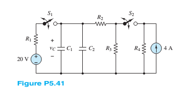
For the circuit shown in Figure P5.41, assume that switches
a Find the capacitor voltage
b. Find the time constant
c. Find
d. Find
e. Find
f. Sketch
Want to see the full answer?
Check out a sample textbook solution
Chapter 5 Solutions
Principles and Applications of Electrical Engineering


- 3. For the R-C circuit in below figure, composed of standard values: a. Determine the time constant of the circuit when the switch is thrown into position 1. b. Find the mathematical expression for the voltage across the capacitor and the current after the switch is thrown into position 1. c. Determine the voltage Vc and current éc the instant the switch is thrown into position 2, t-1s. d. Determine the mathematical equation for voltage Ve and current zc for the discharge phase. R=4.7KO, C=56µF, E=22V + 'R 29 ve (a)arrow_forward2 At t < 0, the circuit shown in Figure P5.22 is at steady state. The switch is changed as shown at t = 0. Vsi = 35 V C = 11 µF Vsz = 130 V R = 17 k2 R2 = 7 k2 R = 23 k2 Determine at t = 0+ the initial current through R just after the switch is changed. 1= 0 R3 Vs1 Vs2arrow_forward1 Just before the switch is opened at t = 0, the current through the inductor is 1.70 mA in the direction shown in Figure P5.21. Did steady-state conditions exist just before the switch was opened? L= 0.9 mH Vs = 12 V R = 6 k2 R2 = 6 k2 R = 3 k2 t = 0 R2 R1 L R3{Va3 V83arrow_forward
- Solve the circuit by obtaining the state equation. The initial condition voltage value of the capacitance element is VC (0) = 1Volt. R1 = R2 = R3 = R4 = 1Ω, E = 3Volt. State the core solution and the forced solution components in the solution you obtained.arrow_forward8 For t > 0, the circuit shown in Figure P5.22 is at steady state. The switch is changed as shown at t = 0. Vsi = 35 V C = 11 µF Vsz = 130 V R = 17 k2 R = 7 k2 R = 23 k2 Determine the time constant of the circuit for t> 0.arrow_forward6 At t< 0, the circuit shown in Figure P5.66 is at steady state, and the voltage across the capacitor is +7 V. The switch is changed as shown at t= 0, and Vs = 12 V C= 3,300 µF R = 9.1 k2 R = 4.3 k2 R3 = 4.3 k2 L= 16 mH Determine the initial voltage across R2 just after the switch is changed. t=0 Le )V½ R R 2 R3 ww-arrow_forward
- 3 Determine the current through the capacitor just before and just after the switch is closed in Figure P5.23. Assume steady-state conditions for t < 0. C = 0.5 µF V = 12 V R = 0.68 k2 R2 = 1.8 k2 t= 0 R2arrow_forward9 At t 0.arrow_forwardFor the circuit shown in Figure Q2, determine the followi (a) The current in the inductors L1 and L2. (b) The voltage across the capacitors Cl and C2. (c) The total energy stored in the circuit. (d) The total power supplied by the source. 30V II RI -000-m 20mH 1052 50mH 2 R2 2002 300µF -000 30ml 91 300µF CI 600 μF R3 30Ω C3arrow_forward
- At 0-, no currrent flows through the capacitors because they are open, how did you combine the capacitors for the voltage divider since it is the capacitance value and not reactance, is it right? Can we just combine the capacitance value? Please explain. I did not understand..arrow_forwardConsider the circuit shown in the figure. The capacitor is initially uncharged. Find the current across R2 after time t.arrow_forward1 Just before the switch is opened at t = 0 in Figure P5.21, the current through the inductor is 1.70 mA in the direction shown. Vs = 12 V L = 0.9 mH R = 6 k2 R2 = 6 k2 R = 3 k2 Determine the time constant of the circuit for t > 0.arrow_forward
 Introductory Circuit Analysis (13th Edition)Electrical EngineeringISBN:9780133923605Author:Robert L. BoylestadPublisher:PEARSON
 Delmar's Standard Textbook Of ElectricityElectrical EngineeringISBN:9781337900348Author:Stephen L. HermanPublisher:Cengage Learning
 Programmable Logic ControllersElectrical EngineeringISBN:9780073373843Author:Frank D. PetruzellaPublisher:McGraw-Hill Education
 Fundamentals of Electric CircuitsElectrical EngineeringISBN:9780078028229Author:Charles K Alexander, Matthew SadikuPublisher:McGraw-Hill Education
 Electric Circuits. (11th Edition)Electrical EngineeringISBN:9780134746968Author:James W. Nilsson, Susan RiedelPublisher:PEARSON
 Engineering ElectromagneticsElectrical EngineeringISBN:9780078028151Author:Hayt, William H. (william Hart), Jr, BUCK, John A.Publisher:Mcgraw-hill Education,