
Concept explainers
Videos
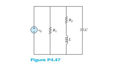
Determine the equivalent impedance seen by the source
Want to see the full answer?
Check out a sample textbook solution
Chapter 4 Solutions
Principles and Applications of Electrical Engineering


- Question No. 4 hand written withn expanation (a) Design a circuit using D flip-flops that can be used to divide the clock frequency by 16. (b) Draw the input and output waveforms for each stage to the circuit designed in part (a).arrow_forwardhandwritten withn expanation need Question No. 4 ( (a) Design a circuit using D flip-flops that can be used to divide the clock frequency by 16. (b) Draw the input and output waveforms for each stage to the circuit designed in part (a).arrow_forwardDraw and explain the electronic circuit diagram of PID controller, Write its advantages anddisadvantages.arrow_forward
- Written Answer Needed Correct onearrow_forwardINSTRUCTIONS: only electrical engineering experts solve it correct take your 5hrs but solve accurate not ai answers okkkk Only Electrical engineering experts solve it okkMention Written Answer Needed Correct onearrow_forwardI need expert solution not Aiarrow_forward
- Question (a) Design a circuit using D flip-flops that can be used to divide the clock frequency by 16. (b) Draw the input and output waveforms for each stage to the circuit designed in part (a).arrow_forwardDon't use ai to answer I will report you answerarrow_forwardCorrect & written Based Need, No Copy Paste Chatgpt Answerarrow_forward
 Introductory Circuit Analysis (13th Edition)Electrical EngineeringISBN:9780133923605Author:Robert L. BoylestadPublisher:PEARSON
 Delmar's Standard Textbook Of ElectricityElectrical EngineeringISBN:9781337900348Author:Stephen L. HermanPublisher:Cengage Learning
 Programmable Logic ControllersElectrical EngineeringISBN:9780073373843Author:Frank D. PetruzellaPublisher:McGraw-Hill Education
 Fundamentals of Electric CircuitsElectrical EngineeringISBN:9780078028229Author:Charles K Alexander, Matthew SadikuPublisher:McGraw-Hill Education
 Electric Circuits. (11th Edition)Electrical EngineeringISBN:9780134746968Author:James W. Nilsson, Susan RiedelPublisher:PEARSON
 Engineering ElectromagneticsElectrical EngineeringISBN:9780078028151Author:Hayt, William H. (william Hart), Jr, BUCK, John A.Publisher:Mcgraw-hill Education,