
Concept explainers
Videos
Solve for
Want to see the full answer?
Check out a sample textbook solution
Chapter 4 Solutions
Principles and Applications of Electrical Engineering


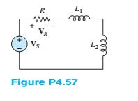
- Find vout (t) for the circuit shown in Figure P4.60. | 102 mA Xz = 1 k2 Vout Xc = 10 k2arrow_forwardUse the superpasition principle to find voltages V 4.6 and V in the circuit shown in Figure P4.6 FIGURE P4.6 25 aarrow_forward3 Determine the equivalent impedance in the circuit shown in Figure P4.47: v,(1) = 636 cos (3,000t + ) v R2 = 22 k2 C = 6.8 nF 12. R = 3.3 k2 L = 1.90 Harrow_forward
- 4.12 Use the superposition principle to find voltuges V, and V in the cireuit shown in Figure P4.12 FIGURE P4.12 л, ko w500arrow_forward7 Solve for V2 in the circuit shown in Figure P4.57. Assume w = 2. 6 H ll 12 Ω ww + Vị +, V = 2520 V 6Ωarrow_forwardhello i need to solve thi question, (Homework problem 4.47 in the textbook by Rizzoni) Determine the equivalent impedance seen by the source vs in Figure P4.47 when: vs (t) = 10 cos(4000t + 60°) V, R1 = 800Ω, R2 = 500Ω, L = 200mH, C = 70nF. I have added the given solution, however, I cannot get the last step correct. anny help would be gadly appreciated.arrow_forward
- A Hay's bridge uses a standard capacitor of C4 = 0.02 mF and operates at a supply frequency of 800 Hz. Balance is achieved when R2 =0.54kn ,R3= 3.8kN, and R4 =100 Q. Find the unknown Resistance R1 and unknown inductance L1. unknown Resistance R1 unknown Inductance L1arrow_forwardDetermine the equivalent inductance and equivalent current of the inductive circuit in Figure Q4. If L5 is replaced with a capacitor of 0.55 mF, how would it affect the branch current? The alternating Voltage source has an amplitude of 25 Vm.arrow_forwardP4.13. Derive an expression for V C ( t) in the circuit of Figure P4.13 and sketch v C(t) to scale versus time. R 10 mA 2 k 10 uF Figure P4.13arrow_forward
- P4.26. The circuit shown in Figure P4.26 is operating in steady state. Determine the values of i L, vx, and v C. 3 k 3 kl 15 mA 7 mH I uF 5 mH 20 V Figure P4.26arrow_forward/Q6 The potential at point P due to Q1 and * :Q2 is = 1x10-12C 0.5 m 0.5 m Q2 = 1x10-12C %3D 50 cm P. 0.01797 V O -0.01271 V O ov O 0.01271 V C 10arrow_forward4.19 Use source transformation to find voltage V, in the circuit shown in Figure P4.19 FIGURE P4.19 2 aOo trancformation to find yoltage V.in Uarrow_forward
 Introductory Circuit Analysis (13th Edition)Electrical EngineeringISBN:9780133923605Author:Robert L. BoylestadPublisher:PEARSON
 Delmar's Standard Textbook Of ElectricityElectrical EngineeringISBN:9781337900348Author:Stephen L. HermanPublisher:Cengage Learning
 Programmable Logic ControllersElectrical EngineeringISBN:9780073373843Author:Frank D. PetruzellaPublisher:McGraw-Hill Education
 Fundamentals of Electric CircuitsElectrical EngineeringISBN:9780078028229Author:Charles K Alexander, Matthew SadikuPublisher:McGraw-Hill Education
 Electric Circuits. (11th Edition)Electrical EngineeringISBN:9780134746968Author:James W. Nilsson, Susan RiedelPublisher:PEARSON
 Engineering ElectromagneticsElectrical EngineeringISBN:9780078028151Author:Hayt, William H. (william Hart), Jr, BUCK, John A.Publisher:Mcgraw-hill Education,