
Concept explainers
Videos
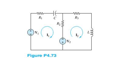
Use mesh analysis to determine the currents
Want to see the full answer?
Check out a sample textbook solution
Chapter 4 Solutions
Principles and Applications of Electrical Engineering


- Using source transformation theorem, solve the current, I, and voltage, V, in Figure Q4. Assume that the operating frequency is 50HZ. 20 mH 1220° V V. 50' 4290 A (*)1045° V F Figure Q4arrow_forwardined EXAMPLE 4.6 A series circuit has R=402 and L=0.01 H. Find the impedance at 100 Hz and 500 Hz.arrow_forward3. For 6 = 100, VBE = 0.7 V and VE = 4 V, determine a. Ic b. VB C. VCE d. R2 VCc 18V Vcc R1 R3 :1 ΜΩ 2kQ 2 Q1 BJT_NPN_VIRTUAL 3 R4 1.0kQ R2 -w-arrow_forward
- Task4. For the T equivalent circuit shown in the figure, form an impedance matrix Z. (Refer to the definition of the voltage equation as follows.) Zz Voltage equations =h+mh U₁ = 11. kun 1=0 U₁ = 12/2. kun 1₁ = 0 U2-21/1, kun /2=0 U-kun =0 Ζι=ΙΩ Z2=2i2 Z3=-30i 2 U₂arrow_forward37 lll a docs.google.com/forms/d/e, 180 KJ 185 kJ 4-For the circuit shown in Figure, Using nodal analysis, to determine the current in (30) ? * SA F16 V ER 16 V 5A O (I= 8 A ) & ( R=2 Q ) (I= - 8 A ) & ( R=4 0) (I= 6 A ) & ( R=4 0) This is a required question Page 2 of 2 Back Submit Never submit passwords through Google Forms. This form was created inside of University of Kerbala. Report Abusearrow_forwardb) Analyse the principles of circuit theory as applied to the circuits illustrated in Figure 4b with sinusoidal sources, to explain the operation of the circuit by determining the phase angle, ZT, IT, IR, IL, P. V=120V, 50Hz R₂=3002 and L=106 H. Vo (t) Figure 4b R2 ww L eeeee Vs (t)arrow_forward
- 4. Find the steady-state voltage gain and do the switch realization for the converter primitives shown below. + (a) Buck². • 1 0 (c) Inverse Watkins-Johnson. V 1 SI 0 (b) Current-fed bridge. 46 Figure 1: Schematics for Question 4. S2 0 (d) Watkins-Johnson.arrow_forwardUsing whatever method you like, find the transfer function of the following system (try to solve it step by step, explaining the procedure): bobina=coil K₁ L R$ e,(1) Bobina B K₂ wwwwwwwarrow_forwardUse the superposition principle to find voltage in the circuit shown in Figure P4.3. 4.3 FIGURE P4.3 3k 2 k 2mA Re 5 R 4 Hiarrow_forward
- Q.4. (a) Analyze the the following circuit and draw the output waveform across resistor R. (b) Again analyze the circuit if D, becomes open circuite, also plot the output waveform. Vi + D1. D2 V. Vo + T R D3 D4arrow_forwardWhat is V4 given R4 = 237.41 MOhms?arrow_forwardUsing mesh analysis to the circuit in the figure below, i, can be obtained approximately as? 14V + 10V Select one: 392 ww a. 4.4615 A b. 5.3077 A c. 0.8462 A d.-5.3077 A www 492 www iz 292arrow_forward
 Introductory Circuit Analysis (13th Edition)Electrical EngineeringISBN:9780133923605Author:Robert L. BoylestadPublisher:PEARSON
 Delmar's Standard Textbook Of ElectricityElectrical EngineeringISBN:9781337900348Author:Stephen L. HermanPublisher:Cengage Learning
 Programmable Logic ControllersElectrical EngineeringISBN:9780073373843Author:Frank D. PetruzellaPublisher:McGraw-Hill Education
 Fundamentals of Electric CircuitsElectrical EngineeringISBN:9780078028229Author:Charles K Alexander, Matthew SadikuPublisher:McGraw-Hill Education
 Electric Circuits. (11th Edition)Electrical EngineeringISBN:9780134746968Author:James W. Nilsson, Susan RiedelPublisher:PEARSON
 Engineering ElectromagneticsElectrical EngineeringISBN:9780078028151Author:Hayt, William H. (william Hart), Jr, BUCK, John A.Publisher:Mcgraw-hill Education,