
Concept explainers
Videos
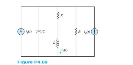
Using phasor techniques to solve for
Want to see the full answer?
Check out a sample textbook solution
Chapter 4 Solutions
Principles and Applications of Electrical Engineering


- /Q6 The potential at point P due to Q1 and * :Q2 is = 1x10-12C 0.5 m 0.5 m Q2 = 1x10-12C %3D 50 cm P. 0.01797 V O -0.01271 V O ov O 0.01271 V C 10arrow_forwardR 2 0 5e-2' cos(31) L 1 H Figure P4.48 If Vg (t) = 5e-2tcos(3t) V, and iL(-)= -0.3A. %3D a. determine the request voltages and currents. VR(0+)= VL(0+)= İL(0+)= b. On a single graph, draw to scale the waveforms of VG(t) and VL(t). c. expression for iL(t), t>0arrow_forwardhello i need to solve thi question, (Homework problem 4.47 in the textbook by Rizzoni) Determine the equivalent impedance seen by the source vs in Figure P4.47 when: vs (t) = 10 cos(4000t + 60°) V, R1 = 800Ω, R2 = 500Ω, L = 200mH, C = 70nF. I have added the given solution, however, I cannot get the last step correct. anny help would be gadly appreciated.arrow_forward
- A Hay's bridge uses a standard capacitor of C4 = 0.02 mF and operates at a supply frequency of 800 Hz. Balance is achieved when R2 =0.54kn ,R3= 3.8kN, and R4 =100 Q. Find the unknown Resistance R1 and unknown inductance L1. unknown Resistance R1 unknown Inductance L1arrow_forwardI have a series circuit with a source of 50V, resistor 400 ohms, capacitor Xc=120 ohms, and a 60 Hz. frequency, I'm looking to find out the Capacitance on the circuit, and the formula to solve the problem, Thanks.arrow_forwardSolve for Ij in the circuit shown in Figure P4.56. I= 102 -A j4 2arrow_forward
- Select an answer4. Two base signals for a quadrature system are:A. sin (w_c t) and cos (2w_c t)B. sin (w_c t) and cos (w_c t)C. sin (1/2 w_c t) and cos (w_c t)D. cos (w_1 t) and cos (w_2 t)arrow_forwardAnswer it clearly Show the complete solution An R-L-C series circuit has a current which lags the applied voltage by 45 degrees. The voltage across the inductance has maximum value equal o twice the maximum value of voltage across the capacitor. Voltage across the inductance is 300 sin (1000t) and R = 20 ohms Find the value of inductance, total impedance and capacitance.arrow_forwardSince V=12V, C1 = C4 = 2uF, C2 = 4uF, C3 = 1uF in the circuit in the figure, what is the charge (in uC) on the capacitor C4?arrow_forward
- Solve the voltages (Vrms) across the resistor and capacitor. Prove that the phasor sum of the series components is equal to the source voltage. Attach your neat and complete solution in the answer sheet. (Vrms)arrow_forwardQUESTION 4 a) Circuit shown in Figure Q4a is a parallel RLC circuit, illustrate the circuit in phasor domain equivalent circuit and hence find the impedances, Zx, Zin and the steady state current ix(t). is(t) = 25 cos 1000t A Zin Vs(t) = 100 cos (20001+60°) V elle 10 Q2 10 mH Figure Q4a -j5Q 1100 mo www 200 Zx b) For the circuit of Figure Q4b, solve for the phasor current io(t), and the real and reactive power supplied by the voltage source, Vs. Figure Q4b ix m0000 50 µF 2002 relle 10 Q 50 mH -10 Qarrow_forwardElectrical Engineering Write an ALP to implement the following P = XY+XZ+XY'Z pls solve as soon as possiblearrow_forward
 Introductory Circuit Analysis (13th Edition)Electrical EngineeringISBN:9780133923605Author:Robert L. BoylestadPublisher:PEARSON
 Delmar's Standard Textbook Of ElectricityElectrical EngineeringISBN:9781337900348Author:Stephen L. HermanPublisher:Cengage Learning
 Programmable Logic ControllersElectrical EngineeringISBN:9780073373843Author:Frank D. PetruzellaPublisher:McGraw-Hill Education
 Fundamentals of Electric CircuitsElectrical EngineeringISBN:9780078028229Author:Charles K Alexander, Matthew SadikuPublisher:McGraw-Hill Education
 Electric Circuits. (11th Edition)Electrical EngineeringISBN:9780134746968Author:James W. Nilsson, Susan RiedelPublisher:PEARSON
 Engineering ElectromagneticsElectrical EngineeringISBN:9780078028151Author:Hayt, William H. (william Hart), Jr, BUCK, John A.Publisher:Mcgraw-hill Education,