
Principles and Applications of Electrical Engineering
6th Edition
ISBN: 9780073529592
Author: Giorgio Rizzoni Professor of Mechanical Engineering, James A. Kearns Dr.
Publisher: McGraw-Hill Education
expand_more
expand_more
format_list_bulleted
Videos
Textbook Question
Chapter 4, Problem 4.28HP
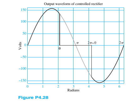
The output voltage waveform of a controlled rectifier is shown in Figure P4.28. The input voltage waveform was a sinusoid of amplitude 110 V rms.Find the average and rms voltages of the output waveform in terms of the firing angle
Expert Solution & Answer
Want to see the full answer?
Check out a sample textbook solution
Students have asked these similar questions
A single phase – half wave controlled rectifier with freewheeling diode is supplying a load consistingseries connected a resistor and an inductance from a 70.7V (RMS), 50Hz sinusoidal AC source.The firing delay of the thyristor is 90° and the load values are R=10Ω, L=0.1 H. Define the loadcurrent expression and draw the load current by calculating for first two periods. And calculate theaverage values of the load voltage and current.
Q4. For the three-phase fully-controlled bridge rectifier circuit shown with purely
resistive load:
a. Sketch the output voltage waveform.
a = 30°
b. Determine the ripple factor & input power factor.
VA= 240 V(V) VB
RL
2202
2n
P4- Consider the bridge rectifier shown in the figure below; with an input voltage vs = 15 sin wt. Assume a diode cut-in
voltage of V₂ = 0.7 V. Determine the fraction percent of time that the diode D₁ is conducting. Sketch the signals and
fraction of time to illustrate your answer. What happens to that fraction if the input signal has a peak value of 3V only?
N₁: N₂
US
D₂
RL
www
Chapter 4 Solutions
Principles and Applications of Electrical Engineering
Ch. 4 - The current through a 0.8-H inductor is given by...Ch. 4 - For each case shown below, derive the expression...Ch. 4 - Derive the expression for the voltage across...Ch. 4 - In the circuit shown in Figure P4.4, assume R=1...Ch. 4 - Prob. 4.5HPCh. 4 - In the circuit shown in Figure P4.4, assume R=2...Ch. 4 - In the circuit shown in Figure P4.7, assume R=2...Ch. 4 - Prob. 4.8HPCh. 4 - Prob. 4.9HPCh. 4 - Prob. 4.10HP
Ch. 4 - The voltage waveform shown in Figure P4.10 is...Ch. 4 - The voltage across a 0.5-mH inductor, Plotted as a...Ch. 4 - Prob. 4.13HPCh. 4 - The current through a 16-H inductor is zero at t=0...Ch. 4 - The voltage across a generic element X has the...Ch. 4 - The plots shown in Figure P4.16 are the voltage...Ch. 4 - The plots shown in Figure P4.17 are the voltage...Ch. 4 - The plots shown in Figure P4.18 are the voltage...Ch. 4 - The plots shown in Figure P4.19 are the voltage...Ch. 4 - The voltage vL(t) across a 10-mH inductor is shown...Ch. 4 - The current through a 2-H inductor is p1otted in...Ch. 4 - Prob. 4.22HPCh. 4 - Prob. 4.23HPCh. 4 - Prob. 4.24HPCh. 4 - The voltage vC(t) across a capacitor is shown in...Ch. 4 - The voltage vL(t) across an inductor is shown in...Ch. 4 - Find the average and rms values of x(t) when:...Ch. 4 - The output voltage waveform of a controlled...Ch. 4 - Refer to Problem 4.28 and find the angle + that...Ch. 4 - Find the ratio between the average and rms value...Ch. 4 - The current through a 1- resistor is shown in...Ch. 4 - Derive the ratio between the average and rms value...Ch. 4 - Find the rms value of the current waveform shown...Ch. 4 - Determine the rms (or effective) value of...Ch. 4 - Assume steady-state conditions and find the energy...Ch. 4 - Assume steady-state conditions and find the energy...Ch. 4 - Find the phasor form of the following functions:...Ch. 4 - Convert the following complex numbers to...Ch. 4 - Convert the rectangular factors to polar form and...Ch. 4 - Complete the following exercises in complex...Ch. 4 - Convert the following expressions to rectangular...Ch. 4 - Find v(t)=v1(t)+v2(t) where...Ch. 4 - The current through and the voltage across a...Ch. 4 - Express the sinusoidal waveform shown in Figure...Ch. 4 - Prob. 4.45HPCh. 4 - Convert the following pairs of voltage and current...Ch. 4 - Determine the equivalent impedance seen by the...Ch. 4 - Determine the equivalent impedance seen by the...Ch. 4 - The generalized version of Ohm’s law for impedance...Ch. 4 - Prob. 4.50HPCh. 4 - Determine the voltage v2(t) across R2 in the...Ch. 4 - Determine the frequency so that the current Ii...Ch. 4 - Prob. 4.53HPCh. 4 - Use phasor techniques to solve for the current...Ch. 4 - Use phasor techniques to solve for the voltage...Ch. 4 - Prob. 4.56HPCh. 4 - Solve for VR shown in Figure P4.57. Assume:...Ch. 4 - With reference to Problem 4.55, find the value of ...Ch. 4 - Find the current iR(t) through the resistor shown...Ch. 4 - Find vout(t) shown in Figure P4.60.Ch. 4 - Find the impedance Z shown in Figure...Ch. 4 - Find the sinusoidal steady-state output vout(t)...Ch. 4 - Determine the voltage vL(t) across the inductor...Ch. 4 - Determine the current iR(t) through the resistor...Ch. 4 - Find the frequency that causes the equivalent...Ch. 4 - a. Find the equivalent impedance Zo seen by the...Ch. 4 - A common model for a practical capacitor has...Ch. 4 - Using phasor techniques, solve for vR2 shown in...Ch. 4 - Using phasor techniques to solve for iL in the...Ch. 4 - Determine the Thévenin equivalent network seen by...Ch. 4 - Determine the Norton equivalent network seen by...Ch. 4 - Use phasor techniques to solve for iL(t) in...Ch. 4 - Use mesh analysis to determine the currents i1(t)...Ch. 4 - Prob. 4.74HPCh. 4 - Prob. 4.75HPCh. 4 - Find the Thévenin equivalent network seen by the...Ch. 4 - Prob. 4.77HPCh. 4 - Prob. 4.78HPCh. 4 - Prob. 4.79HPCh. 4 - Prob. 4.80HPCh. 4 - Use mesh analysis to find the phasor mesh current...Ch. 4 - Write the node equations required to solve for all...Ch. 4 - Determine Vo in the circuit of Figure...Ch. 4 - Prob. 4.84HP
Knowledge Booster


Learn more about
Need a deep-dive on the concept behind this application? Look no further. Learn more about this topic, electrical-engineering and related others by exploring similar questions and additional content below.Similar questions
- In the circuit shown in the figure; A) When RL = 5Kohm and capacitor C is switched on, draw VA and V0 in scale according to input voltage Vs. NOTE = diodes are idealarrow_forwardQ4.a) What is a crystal diode?b) Explain its rectifying action.c) With a neat sketch, explain the working of the following:i. Centre-tap full-wave rectifierii. Full-wave bridge rectifierarrow_forwardQ4. For the three-phase fully-controlled bridge rectifier circuit shown with purely resistive load: a. Sketch the output voltage waveform. a = 60° b. Determine the ripple factor & input power factor. a VA= 220 V(^) VB A-B B-C C-A C-B RL 2202 OT 2narrow_forward
- 4-) In the half-wave rectifier in Figure 4 diode D is ideal. The input v, is a 50-Hz sinusoidal voltage with peak value V, (v,(1) =V, sin(ot) V ). The rectifier feeds a load which draws constant current /, from the rectifier. (a) Derive an expression for the ripple voltage V, in terms of I,, Cand V, (Hint: After the diode turns off att, the capacitor discharges with a constant discharging current i, = -I. Also the discharging time (from t, to t, +T) can be approximated by the period of the sine wave T = Express dv / dt in terms of V, ) (b) With I, =0.1A, C = 200 uF, V, = 100 V calculate V,.( (c) Calculate the conduction angle of the diode oAt.(: (Hint: It may help to review the derivation of wAt for the resistance load case) - Vc V, Figure 4 4+Tarrow_forwardA sinusoidal voltage of peak value 50 V is applied to a diode as shown in the figure. Sketch the waveform of voltage Vo treating the diode as an ideal one.arrow_forwardQ4. a) What is a crystal diode? b) Explain its rectifying action. c) With a neat sketch, explain the working of the following: i. Centre-tap full-wave rectifier ii. Full-wave bridge rectifierarrow_forward
- 14.3 V Answer the following questions, since the minimum voltage value to transmit the zener diode in the figure given above is 9V and the power of this Zener diode is 0.3 watts. a) draw a parallel Clipper circuit that will give the output signal given in the figure. b) enter the name of the parallel Clipper circuit that will give this output voltage.arrow_forward(c) Figure Q2(c) shows the clamper circuit. Given the square wave input voltage, Vin is 30V.- p and diode is an ideal condition. Determine the value of overall output voltage, Vout and the type of clamper circuit. + C - + Vin Vout RL + V1= 5V Figure Q2(c)arrow_forwardQ4- Give a possible applications for a Zener diode ?arrow_forward
- An ac voltage of peak value 20v is connected in series with a silicon diode and load resistance of 5002. if the forward resistance of diode is 102 find: i- Peak current through diode. ii- Peak output voltage. ii- What will be these values if the diode is assumed to be ideal (Vdiode =0)?arrow_forwardIf the diode is ON, what is resistor current and Vo? Assume an ideal diode.arrow_forwardIn a full wave rectifier circuit involving double diodes, a sinusoidal input signal of the following nature is applied e=10 sin(500*pi*t) V. What will be value of the dc voltage obtained at the output of the rectifier.arrow_forward
arrow_back_ios
SEE MORE QUESTIONS
arrow_forward_ios
Recommended textbooks for you
 Introductory Circuit Analysis (13th Edition)Electrical EngineeringISBN:9780133923605Author:Robert L. BoylestadPublisher:PEARSON
 Delmar's Standard Textbook Of ElectricityElectrical EngineeringISBN:9781337900348Author:Stephen L. HermanPublisher:Cengage Learning
 Programmable Logic ControllersElectrical EngineeringISBN:9780073373843Author:Frank D. PetruzellaPublisher:McGraw-Hill Education
 Fundamentals of Electric CircuitsElectrical EngineeringISBN:9780078028229Author:Charles K Alexander, Matthew SadikuPublisher:McGraw-Hill Education
 Electric Circuits. (11th Edition)Electrical EngineeringISBN:9780134746968Author:James W. Nilsson, Susan RiedelPublisher:PEARSON
 Engineering ElectromagneticsElectrical EngineeringISBN:9780078028151Author:Hayt, William H. (william Hart), Jr, BUCK, John A.Publisher:Mcgraw-hill Education,
Introductory Circuit Analysis (13th Edition)
Electrical Engineering
ISBN:9780133923605
Author:Robert L. Boylestad
Publisher:PEARSON
Delmar's Standard Textbook Of Electricity
Electrical Engineering
ISBN:9781337900348
Author:Stephen L. Herman
Publisher:Cengage Learning
Programmable Logic Controllers
Electrical Engineering
ISBN:9780073373843
Author:Frank D. Petruzella
Publisher:McGraw-Hill Education
Fundamentals of Electric Circuits
Electrical Engineering
ISBN:9780078028229
Author:Charles K Alexander, Matthew Sadiku
Publisher:McGraw-Hill Education
Electric Circuits. (11th Edition)
Electrical Engineering
ISBN:9780134746968
Author:James W. Nilsson, Susan Riedel
Publisher:PEARSON
Engineering Electromagnetics
Electrical Engineering
ISBN:9780078028151
Author:Hayt, William H. (william Hart), Jr, BUCK, John A.
Publisher:Mcgraw-hill Education,
19 Power Diodes | Power Electronics; Author: Walid Issa Plus;https://www.youtube.com/watch?v=_E-4bIYlNYQ;License: Standard Youtube License