
Concept explainers
Videos
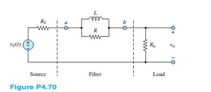
Determine the Thévenin equivalent network seen by the load
and:
a.
b.
Want to see the full answer?
Check out a sample textbook solution
Chapter 4 Solutions
Principles and Applications of Electrical Engineering


- 7 Solve for V2 in the circuit shown in Figure P4.57. Assume w = 2. 6 H ll 12 Ω ww + Vị +, V = 2520 V 6Ωarrow_forwardConsider the circuit in Figure 4. a) Find the Thevenin equivalent of the network connected to the capacitor C1. b) Find the mathematical equations for the transient behavior of voltage vc(t) and the current ic(t) following the closing of the switch. c) Determine the value of voltage vc at t = 100 ms. %3D TC LOSE = 0 R1 TK V1 15V 6K R2 LIK R3 C1 R4 0. 3Karrow_forwardP4.7-15 Determine the values of the mesh currents i₁ and 12 for the circuit shown in Figure P4.7- 15. 4 ia 20 ww ਜਨ 22 ( 1 22 Figure P4.7-15 20 www 12 Varrow_forward
- Derive a star-connected network from the T-connected network shown in the Figure Q4(b) and hence determine the delta-connected equivalent network Z₁=100/00 Z₁=63.25/18.430 23=100-900 Figure Q4(b)arrow_forward4.37 Find the Thévenin equivalent circuit between a and b for the circuit shown in Figure P4.37. FIGURE P4.37 2A 1 Is w R₁ 16 0 HIP R₂ w 8 Ω 8 V R3 8 Ω Vs aarrow_forwardDetermine i₂(t) in the circuit shown in Figure P4.50. Assume: i₁(t) = 100 cos(wt + 4)mA i3(t) = 80 sin(wt - 1.2)mA i4(t)= 150 sin(wt + 2)mA w = 377 rad/s Vs Z₁ i₁ i₂ Z₂ Figure P4.50 14 iz Z 3 Z4arrow_forward
- Q4. Using the nodal-analysis, calculate Vo and Pacn in Figure Q4. 8002 202 402 V. 75V 6A 2002 502 Figure Q4arrow_forward4.19 Use source transformation to find voltage V, in the circuit shown in Figure P4.19 FIGURE P4.19 2 aOo trancformation to find yoltage V.in Uarrow_forward(c) For the network of Figure Q4 (c), R = 700 , L=7 H, C= 1/7 F, Calculate the characteristic roots of the circuit. R L ell V C Figure Q4 (c)arrow_forward
- P 4.4-9 The node voltages in the circuit shown in Figure P 4.4-9 are V₁ = 4 V, v₂ = 0 V, and v3 = -6 V Determine the values of the resistance, R, and of the gain, b, of the CCCS. : U1 10 22 ia Figure P 4.4-9 www 40 S2 10 V +. 02 2022 bia V3 ww Rarrow_forwardQuestion 11: P 4.6-8 Determine values of the mesh currents i1, i2, and iz in the circuit shown in Figure P 4.6-8. 1 k2 iz 2 k2 4 k2 3 v(: O 2 mA iz E1 ka 7 k2 Figure P 4.6-8arrow_forwardUse the mesh current method to calculate the power delivered by the dependent voltage source in the circuit. Figure P4.17 160 V + 10 02 w 30 Ω M 100 Ω 2002 m 150 iarrow_forward
 Introductory Circuit Analysis (13th Edition)Electrical EngineeringISBN:9780133923605Author:Robert L. BoylestadPublisher:PEARSON
 Delmar's Standard Textbook Of ElectricityElectrical EngineeringISBN:9781337900348Author:Stephen L. HermanPublisher:Cengage Learning
 Programmable Logic ControllersElectrical EngineeringISBN:9780073373843Author:Frank D. PetruzellaPublisher:McGraw-Hill Education
 Fundamentals of Electric CircuitsElectrical EngineeringISBN:9780078028229Author:Charles K Alexander, Matthew SadikuPublisher:McGraw-Hill Education
 Electric Circuits. (11th Edition)Electrical EngineeringISBN:9780134746968Author:James W. Nilsson, Susan RiedelPublisher:PEARSON
 Engineering ElectromagneticsElectrical EngineeringISBN:9780078028151Author:Hayt, William H. (william Hart), Jr, BUCK, John A.Publisher:Mcgraw-hill Education,