
Principles and Applications of Electrical Engineering
6th Edition
ISBN: 9780073529592
Author: Giorgio Rizzoni Professor of Mechanical Engineering, James A. Kearns Dr.
Publisher: McGraw-Hill Education
expand_more
expand_more
format_list_bulleted
Concept explainers
Videos
Textbook Question
Chapter 4, Problem 4.21HP
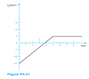
The current through a 2-H inductor is p1otted in Figure P4.2 1. Plot the inductor voltage vL(t) .
Expert Solution & Answer
Want to see the full answer?
Check out a sample textbook solution
Students have asked these similar questions
I need help with this problem and an explanation of the solution for the image described below. (Introduction to Signals and Systems)
How do we know that D1 is forward bias and D2 is reverse biased?
Solve it in a different way than the previous solution that I searched for
Chapter 4 Solutions
Principles and Applications of Electrical Engineering
Ch. 4 - The current through a 0.8-H inductor is given by...Ch. 4 - For each case shown below, derive the expression...Ch. 4 - Derive the expression for the voltage across...Ch. 4 - In the circuit shown in Figure P4.4, assume R=1...Ch. 4 - Prob. 4.5HPCh. 4 - In the circuit shown in Figure P4.4, assume R=2...Ch. 4 - In the circuit shown in Figure P4.7, assume R=2...Ch. 4 - Prob. 4.8HPCh. 4 - Prob. 4.9HPCh. 4 - Prob. 4.10HP
Ch. 4 - The voltage waveform shown in Figure P4.10 is...Ch. 4 - The voltage across a 0.5-mH inductor, Plotted as a...Ch. 4 - Prob. 4.13HPCh. 4 - The current through a 16-H inductor is zero at t=0...Ch. 4 - The voltage across a generic element X has the...Ch. 4 - The plots shown in Figure P4.16 are the voltage...Ch. 4 - The plots shown in Figure P4.17 are the voltage...Ch. 4 - The plots shown in Figure P4.18 are the voltage...Ch. 4 - The plots shown in Figure P4.19 are the voltage...Ch. 4 - The voltage vL(t) across a 10-mH inductor is shown...Ch. 4 - The current through a 2-H inductor is p1otted in...Ch. 4 - Prob. 4.22HPCh. 4 - Prob. 4.23HPCh. 4 - Prob. 4.24HPCh. 4 - The voltage vC(t) across a capacitor is shown in...Ch. 4 - The voltage vL(t) across an inductor is shown in...Ch. 4 - Find the average and rms values of x(t) when:...Ch. 4 - The output voltage waveform of a controlled...Ch. 4 - Refer to Problem 4.28 and find the angle + that...Ch. 4 - Find the ratio between the average and rms value...Ch. 4 - The current through a 1- resistor is shown in...Ch. 4 - Derive the ratio between the average and rms value...Ch. 4 - Find the rms value of the current waveform shown...Ch. 4 - Determine the rms (or effective) value of...Ch. 4 - Assume steady-state conditions and find the energy...Ch. 4 - Assume steady-state conditions and find the energy...Ch. 4 - Find the phasor form of the following functions:...Ch. 4 - Convert the following complex numbers to...Ch. 4 - Convert the rectangular factors to polar form and...Ch. 4 - Complete the following exercises in complex...Ch. 4 - Convert the following expressions to rectangular...Ch. 4 - Find v(t)=v1(t)+v2(t) where...Ch. 4 - The current through and the voltage across a...Ch. 4 - Express the sinusoidal waveform shown in Figure...Ch. 4 - Prob. 4.45HPCh. 4 - Convert the following pairs of voltage and current...Ch. 4 - Determine the equivalent impedance seen by the...Ch. 4 - Determine the equivalent impedance seen by the...Ch. 4 - The generalized version of Ohm’s law for impedance...Ch. 4 - Prob. 4.50HPCh. 4 - Determine the voltage v2(t) across R2 in the...Ch. 4 - Determine the frequency so that the current Ii...Ch. 4 - Prob. 4.53HPCh. 4 - Use phasor techniques to solve for the current...Ch. 4 - Use phasor techniques to solve for the voltage...Ch. 4 - Prob. 4.56HPCh. 4 - Solve for VR shown in Figure P4.57. Assume:...Ch. 4 - With reference to Problem 4.55, find the value of ...Ch. 4 - Find the current iR(t) through the resistor shown...Ch. 4 - Find vout(t) shown in Figure P4.60.Ch. 4 - Find the impedance Z shown in Figure...Ch. 4 - Find the sinusoidal steady-state output vout(t)...Ch. 4 - Determine the voltage vL(t) across the inductor...Ch. 4 - Determine the current iR(t) through the resistor...Ch. 4 - Find the frequency that causes the equivalent...Ch. 4 - a. Find the equivalent impedance Zo seen by the...Ch. 4 - A common model for a practical capacitor has...Ch. 4 - Using phasor techniques, solve for vR2 shown in...Ch. 4 - Using phasor techniques to solve for iL in the...Ch. 4 - Determine the Thévenin equivalent network seen by...Ch. 4 - Determine the Norton equivalent network seen by...Ch. 4 - Use phasor techniques to solve for iL(t) in...Ch. 4 - Use mesh analysis to determine the currents i1(t)...Ch. 4 - Prob. 4.74HPCh. 4 - Prob. 4.75HPCh. 4 - Find the Thévenin equivalent network seen by the...Ch. 4 - Prob. 4.77HPCh. 4 - Prob. 4.78HPCh. 4 - Prob. 4.79HPCh. 4 - Prob. 4.80HPCh. 4 - Use mesh analysis to find the phasor mesh current...Ch. 4 - Write the node equations required to solve for all...Ch. 4 - Determine Vo in the circuit of Figure...Ch. 4 - Prob. 4.84HP
Knowledge Booster


Learn more about
Need a deep-dive on the concept behind this application? Look no further. Learn more about this topic, electrical-engineering and related others by exploring similar questions and additional content below.Similar questions
- A lossless uncharged transmission line of length L = 0.45 cm has a characteristic impedance of 60 ohms. It is driven by an ideal voltage generator producing a pulse of amplitude 10V and width 2 nS. If the transmission line is connected to a load of 200 ohms, sketch the voltage at the load as a function of time for the interval 0 < t < 20 nS. You may assume that the propagation velocity of the transmission is c/2. Answered now answer number 2. Repeat Q.1 but now assume the width of the pulse produced by the generator is 4 nS. Sketch the voltage at the load as a function of time for 0 < t < 20 nS.arrow_forwardSolve this experiment with an accurate solution, please. Thank you.arrow_forwardA lossless uncharged transmission line of characteristic impedance Zo = 600 and length T = 1us is connected to a 180 load. If this transmission line is connected at t = 0 to a 90 V dc source with an internal resistance of 900, from a bounce diagram of this system sketch (a) the voltage at z=0, z=L, and z = L/2 for up to 7.25μs and (b) calculate the load voltage after an infinite amount of time.arrow_forward
- A lossless uncharged transmission line of length L = 0.45 cm has a characteristic impedance of 60 ohms. It is driven by an ideal voltage generator producing a pulse of amplitude 10V and width 2 nS. If the transmission line is connected to a load of 200 ohms, sketch the voltage at the load as a function of time for the interval 0 < t < 20 nS. You may assume that the propagation velocity of the transmission is c/2.arrow_forwardThe VSWR (Voltage Standing Wave Ratio) is measured to be 2 on a transmission line. Find two values of the reflection coefficient with one corresponding to Z > Zo and the other to Zarrow_forwardA dc voltage of unknown value Vand internal resistance Reis connected through a switch to a lossless transmission line of Zo = 1000. If the first 5 μS of the voltages at z = 0 and z = L are observed to be as shown below, calculate Vo, RG, the load resistanceR,, and the transit time T. 100 + [V]:-0. V 90 [V]:-V 100 75 I, Տ 1,μs 2 4 6 0 2 4 6arrow_forward
- A lossless open circuited transmission line behaves as an equivalent capacitance of Ceq = Tan (BL) Show for BL << 1 that Ceq = C'L where L is the length of the transmission line and wZo C' is the lumped parameter capacitance per unit length of the transmission line. Hint: For x small, Tan(x) = x.arrow_forward= A generator with VG 300V and R = 50 is connected to a load R = 750 through a 50 lossless transmission line of length L = 0.15 m. (a) Compute Zin, the input impedance of the line at the generator end. (b) Compute and V. (c) Compute the time-average power Pin delivered to the line. (d) Compute VL, IL, and the time-average power delivered to the load, PL (e) How does Pin compare to PL? Explain.arrow_forwardFor the regulated power supply circuit, assume regular diodes with 0.7V forward drop. Use a 15V (peak), 60Hz sine wave at the transformer secondary and assume a maximum ripple level of 1V. (a) Compute the unknown components needed to design 10V DC supply.Hint: find R first, and then C. What is the ripple level for C=22µF?Sketch the rectified, filtered, and regulated outputsarrow_forward
- A) Find the solution of B) Find the convolution of Sewt (t-π)dt 8 e-atu(t)e-blu(t)arrow_forwardConsider the signal: f(t)= 0, ㅠ 1 Use the Fourier transform formula to find F(w). otherwisearrow_forwardA half-wave controlled rectifier is supplied by a 230 Vrms voltage source and has load resistance of 2502. Calculate the delay angle a that produces a load-absorbed power of 200W.arrow_forward
arrow_back_ios
SEE MORE QUESTIONS
arrow_forward_ios
Recommended textbooks for you
 Introductory Circuit Analysis (13th Edition)Electrical EngineeringISBN:9780133923605Author:Robert L. BoylestadPublisher:PEARSON
 Delmar's Standard Textbook Of ElectricityElectrical EngineeringISBN:9781337900348Author:Stephen L. HermanPublisher:Cengage Learning
 Programmable Logic ControllersElectrical EngineeringISBN:9780073373843Author:Frank D. PetruzellaPublisher:McGraw-Hill Education
 Fundamentals of Electric CircuitsElectrical EngineeringISBN:9780078028229Author:Charles K Alexander, Matthew SadikuPublisher:McGraw-Hill Education
 Electric Circuits. (11th Edition)Electrical EngineeringISBN:9780134746968Author:James W. Nilsson, Susan RiedelPublisher:PEARSON
 Engineering ElectromagneticsElectrical EngineeringISBN:9780078028151Author:Hayt, William H. (william Hart), Jr, BUCK, John A.Publisher:Mcgraw-hill Education,
Introductory Circuit Analysis (13th Edition)
Electrical Engineering
ISBN:9780133923605
Author:Robert L. Boylestad
Publisher:PEARSON
Delmar's Standard Textbook Of Electricity
Electrical Engineering
ISBN:9781337900348
Author:Stephen L. Herman
Publisher:Cengage Learning
Programmable Logic Controllers
Electrical Engineering
ISBN:9780073373843
Author:Frank D. Petruzella
Publisher:McGraw-Hill Education
Fundamentals of Electric Circuits
Electrical Engineering
ISBN:9780078028229
Author:Charles K Alexander, Matthew Sadiku
Publisher:McGraw-Hill Education
Electric Circuits. (11th Edition)
Electrical Engineering
ISBN:9780134746968
Author:James W. Nilsson, Susan Riedel
Publisher:PEARSON
Engineering Electromagnetics
Electrical Engineering
ISBN:9780078028151
Author:Hayt, William H. (william Hart), Jr, BUCK, John A.
Publisher:Mcgraw-hill Education,
Capacitors Explained - The basics how capacitors work working principle; Author: The Engineering Mindset;https://www.youtube.com/watch?v=X4EUwTwZ110;License: Standard YouTube License, CC-BY