
Principles and Applications of Electrical Engineering
6th Edition
ISBN: 9780073529592
Author: Giorgio Rizzoni Professor of Mechanical Engineering, James A. Kearns Dr.
Publisher: McGraw-Hill Education
expand_more
expand_more
format_list_bulleted
Concept explainers
Videos
Textbook Question
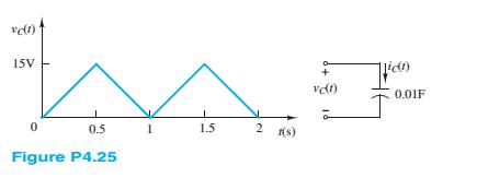
Chapter 4, Problem 4.25HP
The voltage
Expert Solution & Answer
Want to see the full answer?
Check out a sample textbook solution
Students have asked these similar questions
The voltage v(t) shown in Figure P4.22 is appliedto a 10-mH inductor. Find the current through theinductor. Assume iL(0) = 0A.
The initial voltage across the capacitor shown in Figure P4.3 is v C ( 0+ )=0. Find an expression for the voltage across the capacitor as a function of time, and sketch to scale versus time
The voltage waveform shown in Figure P4.24appears across a 100-mH inductor and a 500-μFcapacitor. Plot the capacitor and inductor currents,iC(t) and iL(t), assuming iL(0) = 0A.
Chapter 4 Solutions
Principles and Applications of Electrical Engineering
Ch. 4 - The current through a 0.8-H inductor is given by...Ch. 4 - For each case shown below, derive the expression...Ch. 4 - Derive the expression for the voltage across...Ch. 4 - In the circuit shown in Figure P4.4, assume R=1...Ch. 4 - Prob. 4.5HPCh. 4 - In the circuit shown in Figure P4.4, assume R=2...Ch. 4 - In the circuit shown in Figure P4.7, assume R=2...Ch. 4 - Prob. 4.8HPCh. 4 - Prob. 4.9HPCh. 4 - Prob. 4.10HP
Ch. 4 - The voltage waveform shown in Figure P4.10 is...Ch. 4 - The voltage across a 0.5-mH inductor, Plotted as a...Ch. 4 - Prob. 4.13HPCh. 4 - The current through a 16-H inductor is zero at t=0...Ch. 4 - The voltage across a generic element X has the...Ch. 4 - The plots shown in Figure P4.16 are the voltage...Ch. 4 - The plots shown in Figure P4.17 are the voltage...Ch. 4 - The plots shown in Figure P4.18 are the voltage...Ch. 4 - The plots shown in Figure P4.19 are the voltage...Ch. 4 - The voltage vL(t) across a 10-mH inductor is shown...Ch. 4 - The current through a 2-H inductor is p1otted in...Ch. 4 - Prob. 4.22HPCh. 4 - Prob. 4.23HPCh. 4 - Prob. 4.24HPCh. 4 - The voltage vC(t) across a capacitor is shown in...Ch. 4 - The voltage vL(t) across an inductor is shown in...Ch. 4 - Find the average and rms values of x(t) when:...Ch. 4 - The output voltage waveform of a controlled...Ch. 4 - Refer to Problem 4.28 and find the angle + that...Ch. 4 - Find the ratio between the average and rms value...Ch. 4 - The current through a 1- resistor is shown in...Ch. 4 - Derive the ratio between the average and rms value...Ch. 4 - Find the rms value of the current waveform shown...Ch. 4 - Determine the rms (or effective) value of...Ch. 4 - Assume steady-state conditions and find the energy...Ch. 4 - Assume steady-state conditions and find the energy...Ch. 4 - Find the phasor form of the following functions:...Ch. 4 - Convert the following complex numbers to...Ch. 4 - Convert the rectangular factors to polar form and...Ch. 4 - Complete the following exercises in complex...Ch. 4 - Convert the following expressions to rectangular...Ch. 4 - Find v(t)=v1(t)+v2(t) where...Ch. 4 - The current through and the voltage across a...Ch. 4 - Express the sinusoidal waveform shown in Figure...Ch. 4 - Prob. 4.45HPCh. 4 - Convert the following pairs of voltage and current...Ch. 4 - Determine the equivalent impedance seen by the...Ch. 4 - Determine the equivalent impedance seen by the...Ch. 4 - The generalized version of Ohm’s law for impedance...Ch. 4 - Prob. 4.50HPCh. 4 - Determine the voltage v2(t) across R2 in the...Ch. 4 - Determine the frequency so that the current Ii...Ch. 4 - Prob. 4.53HPCh. 4 - Use phasor techniques to solve for the current...Ch. 4 - Use phasor techniques to solve for the voltage...Ch. 4 - Prob. 4.56HPCh. 4 - Solve for VR shown in Figure P4.57. Assume:...Ch. 4 - With reference to Problem 4.55, find the value of ...Ch. 4 - Find the current iR(t) through the resistor shown...Ch. 4 - Find vout(t) shown in Figure P4.60.Ch. 4 - Find the impedance Z shown in Figure...Ch. 4 - Find the sinusoidal steady-state output vout(t)...Ch. 4 - Determine the voltage vL(t) across the inductor...Ch. 4 - Determine the current iR(t) through the resistor...Ch. 4 - Find the frequency that causes the equivalent...Ch. 4 - a. Find the equivalent impedance Zo seen by the...Ch. 4 - A common model for a practical capacitor has...Ch. 4 - Using phasor techniques, solve for vR2 shown in...Ch. 4 - Using phasor techniques to solve for iL in the...Ch. 4 - Determine the Thévenin equivalent network seen by...Ch. 4 - Determine the Norton equivalent network seen by...Ch. 4 - Use phasor techniques to solve for iL(t) in...Ch. 4 - Use mesh analysis to determine the currents i1(t)...Ch. 4 - Prob. 4.74HPCh. 4 - Prob. 4.75HPCh. 4 - Find the Thévenin equivalent network seen by the...Ch. 4 - Prob. 4.77HPCh. 4 - Prob. 4.78HPCh. 4 - Prob. 4.79HPCh. 4 - Prob. 4.80HPCh. 4 - Use mesh analysis to find the phasor mesh current...Ch. 4 - Write the node equations required to solve for all...Ch. 4 - Determine Vo in the circuit of Figure...Ch. 4 - Prob. 4.84HP
Knowledge Booster


Learn more about
Need a deep-dive on the concept behind this application? Look no further. Learn more about this topic, electrical-engineering and related others by exploring similar questions and additional content below.Similar questions
- Use the defining law for a capacitor to find the current iC(t) corresponding to the voltage shown in Figure P4.27. Sketch your result.arrow_forwardWe know that the capacitor shown in Figure P4.11 is charged to a voltage of 10 V priorto t=0.a. Find expressions for the voltage across the capacitor vC(t) and the voltage across theresistor vR(t) for all time.b. Find an expression for the power delivered to the resistor.c. Integrate the power from t=0 to t=∞ to find the energy delivered.d. Show that the energy delivered to the resistor is equal to the energy stored in thecapacitor prior to t=0.arrow_forwardThe plot of time-dependent voltage is shown inFigure P4.12. The waveform is piecewise continuous.If this is the voltage across a capacitor and C = 80 μF,determine the current through the capacitor. How cancurrent flow “through” a capacitor?arrow_forward
- For the circuit shown in Figure (4.a): i) Find the voltage across the capacitor in polar form. ii) Draw the phasor diagram relationship of Vc and Vs. iii) Is this circuit pre-dominantly inductive or capacitive? Why?arrow_forwardhow do i calculate the inverse capacitance and its uncertainty if the capacitance value 1.8748+/- 0.0006. please show steps im using this example to do my other values.arrow_forward6. An inductive circuit of 50-2 resistance and 0.08-H inductance is connected in series with a capacitor across a 200-V, 50-Hz supply. The current taken is 3.8 A leading. Find the value of the capacitor.arrow_forward
- If the waveform shown in Figure P4.15 is thevoltage across a capacitor plotted as a function of timewithvPK = 20V, T = 40 μs, C = 680nFdetermine and plot the waveform for the currentthrough the capacitor as a function of time.arrow_forward3 Determine the voltage across the inductor in the circuit shown in Figure P4.63. 3 mH Vz(f) Vs(f) = 24 cos(1,000?) E wwarrow_forwarda. Show how you would connect all five capacitors to get a maximum capacitance and find the maximum capacitance in terms of C. b. Show how you would connect all five capacitors to get a minimum capacitance and find the minimum capacitance in terms of C.arrow_forward
- The current waveform shown in Figure P4.23 flowsthrough a 2-H inductor. Plot the inductor voltage vL(t).arrow_forwardA capacitor can be used .............................................. in electrical circuits. Which of the followings fit? To regulate the currents To regulate the voltages To store energy by deposition of electric charges To provide energy as passive circuit element To store energy in the form of magnetic field To create time varying voltages and currents To dissipate energy To convert elektrik energy into heat or lightarrow_forwardDescribe the behavior of the capacitor voltage withtime as the capacitor charges. Explain the reason for this behavior.arrow_forward
arrow_back_ios
SEE MORE QUESTIONS
arrow_forward_ios
Recommended textbooks for you
 Introductory Circuit Analysis (13th Edition)Electrical EngineeringISBN:9780133923605Author:Robert L. BoylestadPublisher:PEARSON
 Delmar's Standard Textbook Of ElectricityElectrical EngineeringISBN:9781337900348Author:Stephen L. HermanPublisher:Cengage Learning
 Programmable Logic ControllersElectrical EngineeringISBN:9780073373843Author:Frank D. PetruzellaPublisher:McGraw-Hill Education
 Fundamentals of Electric CircuitsElectrical EngineeringISBN:9780078028229Author:Charles K Alexander, Matthew SadikuPublisher:McGraw-Hill Education
 Electric Circuits. (11th Edition)Electrical EngineeringISBN:9780134746968Author:James W. Nilsson, Susan RiedelPublisher:PEARSON
 Engineering ElectromagneticsElectrical EngineeringISBN:9780078028151Author:Hayt, William H. (william Hart), Jr, BUCK, John A.Publisher:Mcgraw-hill Education,
Introductory Circuit Analysis (13th Edition)
Electrical Engineering
ISBN:9780133923605
Author:Robert L. Boylestad
Publisher:PEARSON
Delmar's Standard Textbook Of Electricity
Electrical Engineering
ISBN:9781337900348
Author:Stephen L. Herman
Publisher:Cengage Learning
Programmable Logic Controllers
Electrical Engineering
ISBN:9780073373843
Author:Frank D. Petruzella
Publisher:McGraw-Hill Education
Fundamentals of Electric Circuits
Electrical Engineering
ISBN:9780078028229
Author:Charles K Alexander, Matthew Sadiku
Publisher:McGraw-Hill Education
Electric Circuits. (11th Edition)
Electrical Engineering
ISBN:9780134746968
Author:James W. Nilsson, Susan Riedel
Publisher:PEARSON
Engineering Electromagnetics
Electrical Engineering
ISBN:9780078028151
Author:Hayt, William H. (william Hart), Jr, BUCK, John A.
Publisher:Mcgraw-hill Education,
Capacitors Explained - The basics how capacitors work working principle; Author: The Engineering Mindset;https://www.youtube.com/watch?v=X4EUwTwZ110;License: Standard YouTube License, CC-BY