
Concept explainers
Videos
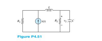
Determine the voltage
Want to see the full answer?
Check out a sample textbook solution
Chapter 4 Solutions
Principles and Applications of Electrical Engineering


- For the following circuit, Vsrc=1.5 V and Rload%3D225 Q. What is the power sourced by the DC voltage supply? Is Vsrc VR Rload 1.5 W 10 mW 81 mW 6.67 mWarrow_forwardFor the following circuit, Vsrc=1.5 V and Rload%3D225 Q. What is Is? Is +. Vsrc VR Rload 30 mA 9 mA 6.67 mA 40 mVarrow_forward20 For the circuit shown in the figure next, Rth (seen by the left side of RL) is found to be (in Ohms) v, 4n Figure X1 None of the choices O 24arrow_forward
- For the circuit shown in figure Req is: * 140 R3 R, R: 22 Rea Ru RC RS R7 33 6 ohm 24.4 ohm 34,4 ohm 44.4 ohmarrow_forwardThe circuit in Figure has been connected for a long time. If the battery is disconnected, how does it take the capacitor to discharge to 1/20 of its initial voltage? Take R₁ = 2.00 Q, R₂=4.00 Q, R3-7.00 Q, R4 = 2.00 Q and C= 5.00 uF and ε = 14.0 V. (Your result must be in us. Include 2 digit after the decimal point and maximum of 2% of error is accepted in your answer.) E R₂ R₂ BAarrow_forwardThe figure shows a circuit that contains five identical resistors with resistance R = 10 ohms, one inductors with inductance L = 4 mH, and an ideal battery with emf = 14V. What is the current I in Amp through the battery long after the switch is closed? R 14 4, mm M Select one: Oa. 2.80A Ob. 0.40A Oc. 9.80A Od. 4.90A Oe. 245Aarrow_forward
- 6. PLEASE SOLVE AND SHOW YOUR DETAILED SOLUTION WITH FBD. The currents at the junction point in a circuit have the following values I1 = (15 – j4) A and I2 = (12 + j22) A. Calculate I1 + I2.arrow_forwardCan someone help me, I can't get right solutions(I will post right solutions at the end)! Capacitors with capacities C1 = 6 pF, C2 = 6 pF, C3 = 12 pF, C4 = 8 pF and C5 = 14 pF are connected according to Figure 4. The source voltage is U =48 V. Determine the charges of capacitors with capacities C1 and C2? right solutions(Q1= 192 pC, Q2= 64 pC) be aware this tasks are for high school(so no division/current rule)arrow_forwardOriginal Schematic and OrCAD Schematic: The input primary voltage is 250V, frequency 50 Hz, primary inductance setting is 2000H and secondary inductance is 10H and voltage peak to peak ripple is approximately equal to 92mv. U1 D4 IN our DINA002 C3 DIN002 90u R1 R2 10k TXI BC540A V1 VOFF =0 VAMPL 2 FREQ- 50 AC0 XFRM_LINICT-SEC D5 DIN4002 C2 0.384m 84 5 HHarrow_forward
- Find the resultant system of converging forces in the 500 N figure. Below 20ON 30ONarrow_forwardDetermine the equivalent inductance and equivalent current of the inductive circuit in Figure Q4. If L5 is replaced with a capacitor of 0.55 mF, how would it affect the branch current? The alternating Voltage source has an amplitude of 25 Vm.arrow_forwardFor R1=1000, R2=6000, R3=6000, R4=4000, C1=0.003, C2=0.002 & 1=0.005 A in the shown circuit, obtain the energy stored in each capacitor under dc conditions. C2 H R4 I1(4 ŽR3 ŽRI C1 Energy stored in C1= Energy stored in C2=arrow_forward
 Introductory Circuit Analysis (13th Edition)Electrical EngineeringISBN:9780133923605Author:Robert L. BoylestadPublisher:PEARSON
 Delmar's Standard Textbook Of ElectricityElectrical EngineeringISBN:9781337900348Author:Stephen L. HermanPublisher:Cengage Learning
 Programmable Logic ControllersElectrical EngineeringISBN:9780073373843Author:Frank D. PetruzellaPublisher:McGraw-Hill Education
 Fundamentals of Electric CircuitsElectrical EngineeringISBN:9780078028229Author:Charles K Alexander, Matthew SadikuPublisher:McGraw-Hill Education
 Electric Circuits. (11th Edition)Electrical EngineeringISBN:9780134746968Author:James W. Nilsson, Susan RiedelPublisher:PEARSON
 Engineering ElectromagneticsElectrical EngineeringISBN:9780078028151Author:Hayt, William H. (william Hart), Jr, BUCK, John A.Publisher:Mcgraw-hill Education,