
Introductory Circuit Analysis (13th Edition)
13th Edition
ISBN: 9780133923605
Author: Robert L. Boylestad
Publisher: PEARSON
expand_more
expand_more
format_list_bulleted
Concept explainers
Videos
Textbook Question
Chapter 24, Problem 52P
For the three-phase, three-wire system in Fig. 24.58, find the magnitude of the current through each phase of the load, and find the total watts, volt-amperes reactive, volt-amperes, and Fp of the load.
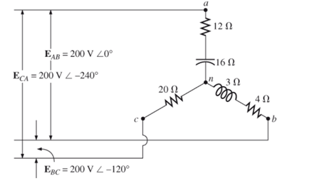
Fig. 24.58
Expert Solution & Answer
Want to see the full answer?
Check out a sample textbook solution
Students have asked these similar questions
2. A cisuuit condirest of rescistance Rohm and an inductanceL
henmy connected to a generator of
the urrent in the ciocuit
Ecoclwr ta) votrage. Fuind
Balanced 3-Phase Voltages
1. Calculate the voltage regulation of a 230V, three phase alternator supplying the following loads connected in wye:a. R = 10 ohmsb. R = 3 ohms, XL = 4 ohmsc. R = 4 ohms, XC = 3 ohmsd. XL = 5 ohmse. XC = 5 ohms2. Calculate the value of each capacitor connected in WYE in part b of number 1 to have zero voltage regulation.
Chapter 24 Solutions
Introductory Circuit Analysis (13th Edition)
Ch. 24 - A balanced V load having a 10 resistance in each...Ch. 24 - Repeat Problem 1 if each phase impedance is...Ch. 24 - Repeat Problem 1 if each phase impedance is...Ch. 24 - The phase sequence for the Y-Y system in Fig....Ch. 24 - Repeat Problem 4 if each phase impedance are...Ch. 24 - Repeat Problem 4 if each phase impedance is...Ch. 24 - For the system in Fig. 24.43, find the magnitude...Ch. 24 - Computer the magnitude of the voltage EAB for the...Ch. 24 - For the Y-Y system in Fig. 24.45: a. Find the...Ch. 24 - For the Y-Y system of Fig. 24.46 the impedance of...
Ch. 24 - A balanced load having a 20 resistance in each...Ch. 24 - Repeat Problem 11 if each phase impedance is...Ch. 24 - Repeat Problem 11 if each phase impedance is...Ch. 24 - The phase sequence for the Y- system in Fig....Ch. 24 - Repeat Problem 14 if each phase impedance is...Ch. 24 - Repeat Problem 14 if each phase impedance are...Ch. 24 - Prob. 17PCh. 24 - For the connected load in Fig. 24.49: a. Find the...Ch. 24 - A balanced V load having a 30 resistance in each...Ch. 24 - Repeat Problem 19 if each phase impedance is...Ch. 24 - Prob. 21PCh. 24 - Prob. 22PCh. 24 - Prob. 23PCh. 24 - Repeat Problem 22 if each phase impedance is...Ch. 24 - Prob. 25PCh. 24 - Prob. 26PCh. 24 - Prob. 27PCh. 24 - The phase sequence for the - system in Fig....Ch. 24 - Repeat Problem 28 if each phase impedance is...Ch. 24 - Repeat Problem 28 if each phase impedance is...Ch. 24 - Prob. 31PCh. 24 - Prob. 32PCh. 24 - Prob. 33PCh. 24 - Find the total watts, volt-amperes reactive,...Ch. 24 - Prob. 35PCh. 24 - Find the total watts, volt-amperes reactive,...Ch. 24 - Find the total watts, volt-amperes reactive,...Ch. 24 - Prob. 38PCh. 24 - Prob. 39PCh. 24 - Find the total watts, volt-amperes reactive,...Ch. 24 - A balanced, three-phase, -connected load has a...Ch. 24 - A balanced, three-phase, Y-connected load has a...Ch. 24 - Find the total watts, volt-amperes reactive,...Ch. 24 - The Y-Y system in Fig. 24.53 has a balanced load...Ch. 24 - Prob. 45PCh. 24 - Prob. 46PCh. 24 - Repeat Problem 46 for the network in Fig. 24.47.Ch. 24 - For the three-wire system in Fig. 24.55, properly...Ch. 24 - Sketch three different ways that two wattmeters...Ch. 24 - For the Y- system in Fig. 24.56: Determine the...Ch. 24 - For the system in Fig. 24.57: Calculate the...Ch. 24 - For the three-phase, three-wire system in Fig....
Knowledge Booster


Learn more about
Need a deep-dive on the concept behind this application? Look no further. Learn more about this topic, electrical-engineering and related others by exploring similar questions and additional content below.Similar questions
- Sample Problems 1. Three identical resistances of 75 ohms are connected in delta across 440 V, 3 phase supply. The value of resistance in each leg of the equivalent star connected load would be ? a) 15 pbmsarrow_forwardIn matlab, To obtain voltage and current waveforms from transmission line which tool can be used O a. voltage measurement O b. Three-phase VI measurment c. Series RLC branch O d. Parallel RLC loadarrow_forward1.3 A 240 volts 50 Hz single phase ac source supplies a series load consisting of a resistor (40 ohms), a reactor (127.324 mH) and a capacitor (318.3 µF). Suppose that the frequency of the source can be varied at will. 1.3.1 Determine the maximum load current. 1.3.2 Determine the source frequency for maximum load current. 1.3.3 What is the name of this frequency? 1.3.4 Determine the load power factor. 1.3.5 What is the name of the sourcearrow_forward
- To have two alternators in parallel, which of the following factors should ?be identical for both Frequency O Voltage, frequency and phase sequence Voltage O Voltage, frequency, phase sequence O and apparent power Phase sequence Oarrow_forwardKhalid Abdulrahman Abdullah Alqasmi KA 05 Symm... 9 Search 8 Share O Comments Transitions Animations Slide Show Review View Help 1. A 3- phase, 30 MVA, 33 KV alternator has internal reactance of 4% and negligible resistance. Find the external reactance per phase to be connected in series with the alternator so that steady current on short circuit does not exceed 10 times the full load. Also find Find the full load current. d notesarrow_forwardA 60Hz, single-phase source with V=27730 volts is applied to a circuit element. (a) Determine the instantaneous source voltage. Also determine the phasor and instantaneous currents entering the positive terminal if the circuit element is (b) a 20 resistor. (C) a 10mH inductor, and (d) a capacitor with 25 reactance.arrow_forward
- a) why is there a wattmeter reading when the load is purely inductiveb) why is there no wattmeter reading when the load is purely capacitivearrow_forwardQ1: A 50HZ,11KV,3-ph,alternator with earthed neutral has a reactance of 50\ph and is connected to bus bar through a C.B.The distributed capacitance up to C.B between phase and neutral is 0.01HF,Determine: 1-The restriking voltage across the contacts of the breaker, 2-The frequency of oscillation,and 3-The voltage across the capacitance. (if the disconnecting capacitive tank)? Q2:Repeat (1,2,and 3) in Q1 if the P.F. of the fault was capacitance current breaking due to 0.4? Q3:Repeat (1,2,and 3) in Q1 if the current chops at an instantaneous rate of 8A?arrow_forwardQ8 During balanced load condition the current flowing through the neutral isarrow_forward
arrow_back_ios
SEE MORE QUESTIONS
arrow_forward_ios
Recommended textbooks for you
 Power System Analysis and Design (MindTap Course ...Electrical EngineeringISBN:9781305632134Author:J. Duncan Glover, Thomas Overbye, Mulukutla S. SarmaPublisher:Cengage Learning
Power System Analysis and Design (MindTap Course ...
Electrical Engineering
ISBN:9781305632134
Author:J. Duncan Glover, Thomas Overbye, Mulukutla S. Sarma
Publisher:Cengage Learning
Fault Analysis in Power Systems part 1a; Author: GeneralPAC: Power System Tutorials;https://www.youtube.com/watch?v=g8itg4MOjok;License: Standard youtube license