
Introductory Circuit Analysis (13th Edition)
13th Edition
ISBN: 9780133923605
Author: Robert L. Boylestad
Publisher: PEARSON
expand_more
expand_more
format_list_bulleted
Concept explainers
Videos
Textbook Question
Chapter 24, Problem 48P
For the three-wire system in Fig. 24.55, properly connect a second wattmeter so that the two measure the total power delivered to the load.
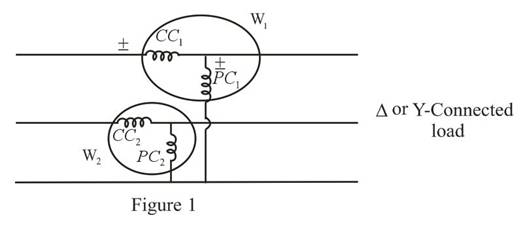
Fig. 24.55
b. If one wattmeter has a reading of 220 W and the other a reading of 85 W, what is the total dissipation in watts if the total power factor is 0.8 leading?
c. Repeat part (b) if the total power factor is 0.2 lagging and
Expert Solution & Answer
Want to see the full answer?
Check out a sample textbook solution
Students have asked these similar questions
1. Calculate the voltage regulation of a 230V, three phase alternator supplying the following loads connected in wye:a. R = 10 ohmsb. R = 3 ohms, XL = 4 ohmsc. R = 4 ohms, XC = 3 ohmsd. XL = 5 ohmse. XC = 5 ohms2. Calculate the value of each capacitor connected in WYE in part b of number 1 to have zero voltage regulation.
1. Find the average power drawn by each charge. Total average power drawn by the loadFind.
2. Find the total average power of the load using the 2 wattmeter method. You find on 1compare with the result.
Q1. If in one cycle (360 degrees), all of instantaneous power falls under positive loops (no negative loops), the load must be:
a.) a resistor
b.) an inductor or capacitor
Explain:
Q2. A wattmeter will indicate zero when the current lags (or leads) the voltage by 90 degrees. Explain
Chapter 24 Solutions
Introductory Circuit Analysis (13th Edition)
Ch. 24 - A balanced V load having a 10 resistance in each...Ch. 24 - Repeat Problem 1 if each phase impedance is...Ch. 24 - Repeat Problem 1 if each phase impedance is...Ch. 24 - The phase sequence for the Y-Y system in Fig....Ch. 24 - Repeat Problem 4 if each phase impedance are...Ch. 24 - Repeat Problem 4 if each phase impedance is...Ch. 24 - For the system in Fig. 24.43, find the magnitude...Ch. 24 - Computer the magnitude of the voltage EAB for the...Ch. 24 - For the Y-Y system in Fig. 24.45: a. Find the...Ch. 24 - For the Y-Y system of Fig. 24.46 the impedance of...
Ch. 24 - A balanced load having a 20 resistance in each...Ch. 24 - Repeat Problem 11 if each phase impedance is...Ch. 24 - Repeat Problem 11 if each phase impedance is...Ch. 24 - The phase sequence for the Y- system in Fig....Ch. 24 - Repeat Problem 14 if each phase impedance is...Ch. 24 - Repeat Problem 14 if each phase impedance are...Ch. 24 - Prob. 17PCh. 24 - For the connected load in Fig. 24.49: a. Find the...Ch. 24 - A balanced V load having a 30 resistance in each...Ch. 24 - Repeat Problem 19 if each phase impedance is...Ch. 24 - Prob. 21PCh. 24 - Prob. 22PCh. 24 - Prob. 23PCh. 24 - Repeat Problem 22 if each phase impedance is...Ch. 24 - Prob. 25PCh. 24 - Prob. 26PCh. 24 - Prob. 27PCh. 24 - The phase sequence for the - system in Fig....Ch. 24 - Repeat Problem 28 if each phase impedance is...Ch. 24 - Repeat Problem 28 if each phase impedance is...Ch. 24 - Prob. 31PCh. 24 - Prob. 32PCh. 24 - Prob. 33PCh. 24 - Find the total watts, volt-amperes reactive,...Ch. 24 - Prob. 35PCh. 24 - Find the total watts, volt-amperes reactive,...Ch. 24 - Find the total watts, volt-amperes reactive,...Ch. 24 - Prob. 38PCh. 24 - Prob. 39PCh. 24 - Find the total watts, volt-amperes reactive,...Ch. 24 - A balanced, three-phase, -connected load has a...Ch. 24 - A balanced, three-phase, Y-connected load has a...Ch. 24 - Find the total watts, volt-amperes reactive,...Ch. 24 - The Y-Y system in Fig. 24.53 has a balanced load...Ch. 24 - Prob. 45PCh. 24 - Prob. 46PCh. 24 - Repeat Problem 46 for the network in Fig. 24.47.Ch. 24 - For the three-wire system in Fig. 24.55, properly...Ch. 24 - Sketch three different ways that two wattmeters...Ch. 24 - For the Y- system in Fig. 24.56: Determine the...Ch. 24 - For the system in Fig. 24.57: Calculate the...Ch. 24 - For the three-phase, three-wire system in Fig....
Knowledge Booster


Learn more about
Need a deep-dive on the concept behind this application? Look no further. Learn more about this topic, electrical-engineering and related others by exploring similar questions and additional content below.Similar questions
- Two alternators A and B deliver 100 and 150 A, respectively to a load. If these current are out pf phase by 30 electrical degrees, determine the total current drawn by the load. A) 241.8 A B ) 201.5 A (c) 250.0 A D) 215.4 Aarrow_forward3. A step down chopper has Vs = 230 V and R = 10 2. For a duty cycle of 0.4, the power taken by the chopper is 2097 Watts. Find the chopper efficiency. Take the voltage drop across the chopper switch as 2 V. 98 % b) 89.96 % c) 99.14 % d) 96.54 %arrow_forwardAn electromagnet consists of a coil with a laminated core assembly. This device takes 6 A when connected to a 120 V DC course. When energized from a 120 V, 60 Hz AC source, the current is 2 A. The wattmeter reads 100 W. Determine the true ohmic resistance of the coil and the effective resistance of the coil. Explain why there is a difference between the true ohmic resistance and the effective resistance values for the same coil windingarrow_forward
- 7. An electromagnet consists of a coil with a laminated core assembly. This device takes 6 A when connected to a 120 V DC course. When energized from a 120 V, 60 Hz AC source, the current is 2 A. The wattmeter reads 100 W. a. Determine the true ohmic resistance of the coil and the effective resistance of the coil. b. Explain why there is a difference between the true ohmic resistance and the effective resistance values for the same coil winding.arrow_forwardA 1500 kvA, 3Φ star-connected alternator, 50 Hz,2300 V alternator has a resistance between each pair of terminals as measured by direct currents is 0.16 ohm. Assume that the effective resistance is 1.5 times the ohmic value. A field current of 70 A produces a short-circuit current equal to full load current of 376 A in each line. The same field current produces an emf of 700 V on open circuit. Determine the synchronous reactance of the machine and its full load voltage regulation at 0.8 power factor lagging. [Ans. VR = 22.8 %]arrow_forwarda) why is there a wattmeter reading when the load is purely inductiveb) why is there no wattmeter reading when the load is purely capacitivearrow_forward
- Answer the following problems in a short/long bond paper size. Round off your answer up to 2 decimals, if applicable. Show your complete solution and box your final answer. You may not copy the problem. 1. Two properly connected wattmeters are used to measure the power drawn by a 440 V squirrel-cage induction motor. If the wattmeters read 60 kW and 32 kW, find the line current drawn by the motor. 2. A 3-phase feeder carries two lagging balanced loads. The power drawn in each is measured by a standard two wattmeter method, giving the following readings: First load: W; = 160 kW; W2 = 96 KW and second load: W. = 90 kW; W; = 48 KW. Find the total kVA load on the feeder. 3. Two-wattmeter method is used to test a 25 hp, 230 V, 1800 rpm, 60 Hz, 3-phase induction motor. If the readings of the wattmeters are 13,400 Ww and 7,400 W, find the power factor of the load. 4. The input power to a 3-phase induction motor running without a load is measured by a two wattmeter method. One wattmeter reads…arrow_forwardAn alternator is connected in star. If the phase voltage is 110 V, the line voltage is *arrow_forwardFor a 3 phase 975 KVA generator.... if the voltage rating is 2400V what is the current rating at each power factor? 1. Unity power factor 2. 80% power factor 3. 50% power factorarrow_forward
- For the circuit shown in Figure 2.24, compute the voltage across the load terminals.arrow_forward1. Draw the waveform for Single Phase Power Supply and find the frequency if the time taken for 10 cycles is 10sec.arrow_forwardb) Suppose that the two-wattmeter method is used to measure the total power of a three-phase three-wire system. The two wattmeter readings are P₁ = +3750 W and P₂= +2350 W. What is the reactive power in the system? o 1.40 kvar o 2.42 kvar O 10.57 kvar o 808.3 vararrow_forward
arrow_back_ios
SEE MORE QUESTIONS
arrow_forward_ios
Recommended textbooks for you
 Power System Analysis and Design (MindTap Course ...Electrical EngineeringISBN:9781305632134Author:J. Duncan Glover, Thomas Overbye, Mulukutla S. SarmaPublisher:Cengage Learning
Power System Analysis and Design (MindTap Course ...
Electrical Engineering
ISBN:9781305632134
Author:J. Duncan Glover, Thomas Overbye, Mulukutla S. Sarma
Publisher:Cengage Learning
Electrical Measuring Instruments - Testing Equipment Electrical - Types of Electrical Meters; Author: Learning Engineering;https://www.youtube.com/watch?v=gkeJzRrwe5k;License: Standard YouTube License, CC-BY
01 - Instantaneous Power in AC Circuit Analysis (Electrical Engineering); Author: Math and Science;https://www.youtube.com/watch?v=If25y4Nhvw4;License: Standard YouTube License, CC-BY