
Videos
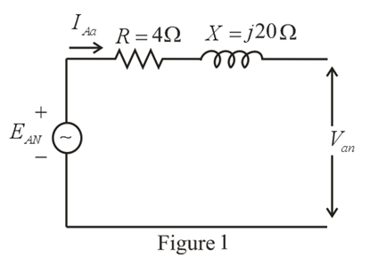
The Y-Y system in Fig. 24.53 has a balanced load and a line impedance
a. The magnitude of each phase voltage of the generator.
b. The magnitude of the line currents.
c. The total power delivered by the source.
d. The power factor angle of the entire load "seen" by the source.
e. The magnitude and angle of the current if
f The magnitude and angle of the phase voltage Van
g. The impedance of the load of each phase in rectangular coordinates.
h. The difference between the power factor of the load and the power factor of the entire system (including Zline.
i. The efficiency of the system.
Want to see the full answer?
Check out a sample textbook solution
Chapter 24 Solutions
Introductory Circuit Analysis (13th Edition)


- In a 3-phase - Y- connected generator, each phase voltage has a magnitude of 90 Vrms, what is the magnitude of each line voltage Select one: O a. None of these O b. 90 Vrms O c. 180 Vrms O d. 156 Vrms TOSHIBAarrow_forwardIn a three phase Y connected generator, the phase voltages are 2 kV. The magnitudes of the line voltages are Select one: O a. 3464 V O b. 6000 V C. 2000 V d. None of thesearrow_forwardCan you explain the given questions in an original way? Single Phase and Three Phase Principles • Single Phase Generators • Two Phase Generatorsarrow_forward
- ΕΧΑMPLE 23.1 The phase sequence of the Y-connected generator in the following figure is ABC. A an 30 EAB EAN 120 V 20° 4Ω Balanced load 40 V bn IN Ven eleee 120 V 203 120 V L02 3Ω 3 N ECN EBN ECA Igb B EBC Ice а) Find the phase angles 0,and 0,. [Ans: 0,= -120° and 0,= 120°] b) Find the magnitude of the line voltages. [Ans: 208 V] Find the line currents. [Ans: I „= 24 AL – 53.13° = 24 AL -173.13° c) Aa I= 24 A266.87° d) Verify that, since the load is balanced, /,= 0.arrow_forwardIf in a Y- connected ac generator, each phase voltage has a magnitude of 90 Vrms, what is the magnitude of each line voltage Select one: O a. 180 Vrms O b. None of these O c. 155.88 Vrms O d. 90 Vrms Jimarrow_forwardThree 230 V generators form a delta connected source that is connected to a balanced load of ZL = 10 + j8 Q per phase as shown in Figure below. (a) Determine the value of IAC (b) What is the value of IbB? a A 230/120° 230/0° b B C 230-120°arrow_forward
- A generator having emf 7sint Volts is connected in series with 8 Ohm resistor and an inductor of 2 Henrys. Find b) the current, I after 15 minutes.arrow_forwardAnswer the question the below Image. A single phase transmission line is delivering 500 kVA load at 2 kv. Its resistance is 0-20 and inductive reactance is 0-40. Determine the voltage regulation if the load power factor is 0-707 lagging. O 8.5 % O 7.2 % O 6.4 % O 5.3 % Continuearrow_forwardA star connected three phase alternator supplies power to a delta connected resistive load. The alternator has a line voltage of 480V. Each resistor of delta load has 8 ohm of resistance. Find the following values. Line voltage of the load (VL(load)) Phase voltage of the load (VP(load)) Phase current of the load (IP(load)) Line current delivered by the alternator (IL(alt)) Phase current of the alternator (IP(Alt)) Phase voltage of the alternator (VP(Alt)) True powerarrow_forward
- For a 3 phase 975 KVA generator.... if the voltage rating is 2400V what is the current rating at each power factor? 1. Unity power factor 2. 80% power factor 3. 50% power factorarrow_forwardKnowing that the voltage Van at the terminals of a three-phase generator without load is 110<25° Vrms calculate the voltage a)Vbc b) Vcn c) Vacarrow_forwardTwo parallel connected loads A and B are supplied by a 440 V line to line, 3-phase, 60 Hz generator. Load A draws an apparent power of 100 kVA at 0.80 pf lagging and load B draws an apparent power of 70 kVA at unity pf. Determine the line current supplied by the source.arrow_forward
 Power System Analysis and Design (MindTap Course ...Electrical EngineeringISBN:9781305632134Author:J. Duncan Glover, Thomas Overbye, Mulukutla S. SarmaPublisher:Cengage Learning