
Introductory Circuit Analysis (13th Edition)
13th Edition
ISBN: 9780133923605
Author: Robert L. Boylestad
Publisher: PEARSON
expand_more
expand_more
format_list_bulleted
Concept explainers
Videos
Textbook Question
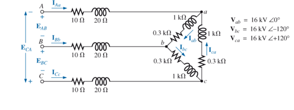
Chapter 24, Problem 18P
For the
a. Find the magnitude and angle of each phase current lab, Ibc, and lca.
b. Calculate the magnitude and angle of each line current lAa, lBb, and lCc.
c. Determine the magnitude and angle of the voltages EAB, EBC, and ECA.
Expert Solution & Answer
Want to see the full answer?
Check out a sample textbook solution
Students have asked these similar questions
Derive the relationship between in case of star and delta connected load between:
a). Phase voltage and line voltage
b). Phase current and line current
Using Kirchhoff’s Law, determine the load currents (IA, IB, IC, ID, IE, IF, and IG).
Consider a 10 kVA, 200/400 V, 50 HZ: single-phase tranformer has the folloving test results:0.C. test: 200 V, 0.6A, 63 W (L.V.side)S.C. test : 20 V, 25A, 85 W (H.V. side)Deternine:i- The eficiengy at 75 % offiull-load at 0.9 leading power factor.ii -The secondary terminal voltage on fill-load at tunity power facton
Chapter 24 Solutions
Introductory Circuit Analysis (13th Edition)
Ch. 24 - A balanced V load having a 10 resistance in each...Ch. 24 - Repeat Problem 1 if each phase impedance is...Ch. 24 - Repeat Problem 1 if each phase impedance is...Ch. 24 - The phase sequence for the Y-Y system in Fig....Ch. 24 - Repeat Problem 4 if each phase impedance are...Ch. 24 - Repeat Problem 4 if each phase impedance is...Ch. 24 - For the system in Fig. 24.43, find the magnitude...Ch. 24 - Computer the magnitude of the voltage EAB for the...Ch. 24 - For the Y-Y system in Fig. 24.45: a. Find the...Ch. 24 - For the Y-Y system of Fig. 24.46 the impedance of...
Ch. 24 - A balanced load having a 20 resistance in each...Ch. 24 - Repeat Problem 11 if each phase impedance is...Ch. 24 - Repeat Problem 11 if each phase impedance is...Ch. 24 - The phase sequence for the Y- system in Fig....Ch. 24 - Repeat Problem 14 if each phase impedance is...Ch. 24 - Repeat Problem 14 if each phase impedance are...Ch. 24 - Prob. 17PCh. 24 - For the connected load in Fig. 24.49: a. Find the...Ch. 24 - A balanced V load having a 30 resistance in each...Ch. 24 - Repeat Problem 19 if each phase impedance is...Ch. 24 - Prob. 21PCh. 24 - Prob. 22PCh. 24 - Prob. 23PCh. 24 - Repeat Problem 22 if each phase impedance is...Ch. 24 - Prob. 25PCh. 24 - Prob. 26PCh. 24 - Prob. 27PCh. 24 - The phase sequence for the - system in Fig....Ch. 24 - Repeat Problem 28 if each phase impedance is...Ch. 24 - Repeat Problem 28 if each phase impedance is...Ch. 24 - Prob. 31PCh. 24 - Prob. 32PCh. 24 - Prob. 33PCh. 24 - Find the total watts, volt-amperes reactive,...Ch. 24 - Prob. 35PCh. 24 - Find the total watts, volt-amperes reactive,...Ch. 24 - Find the total watts, volt-amperes reactive,...Ch. 24 - Prob. 38PCh. 24 - Prob. 39PCh. 24 - Find the total watts, volt-amperes reactive,...Ch. 24 - A balanced, three-phase, -connected load has a...Ch. 24 - A balanced, three-phase, Y-connected load has a...Ch. 24 - Find the total watts, volt-amperes reactive,...Ch. 24 - The Y-Y system in Fig. 24.53 has a balanced load...Ch. 24 - Prob. 45PCh. 24 - Prob. 46PCh. 24 - Repeat Problem 46 for the network in Fig. 24.47.Ch. 24 - For the three-wire system in Fig. 24.55, properly...Ch. 24 - Sketch three different ways that two wattmeters...Ch. 24 - For the Y- system in Fig. 24.56: Determine the...Ch. 24 - For the system in Fig. 24.57: Calculate the...Ch. 24 - For the three-phase, three-wire system in Fig....
Knowledge Booster


Learn more about
Need a deep-dive on the concept behind this application? Look no further. Learn more about this topic, electrical-engineering and related others by exploring similar questions and additional content below.Similar questions
- With a D.C. generator which of the following regulation is preferred ? None of these 100% 50% 1%arrow_forward1.3 A 240 volts 50 Hz single phase ac source supplies a series load consisting of a resistor (40 ohms), a reactor (127.324 mH) and a capacitor (318.3 µF). Suppose that the frequency of the source can be varied at will. 1.3.1 Determine the maximum load current. 1.3.2 Determine the source frequency for maximum load current. 1.3.3 What is the name of this frequency? 1.3.4 Determine the load power factor. 1.3.5 What is the name of the sourcearrow_forwardA parallel connection of a RL branch with a C branch is connected across a 100V AC mains. At first R = 10 ohms, L = 20mH and frequency of 1000rad / s, the current measured is 2.2361A at 89.44 leading power factor. A) Determine the initial capacitance. B) However, a fault occurs on the capacitor branch making its capacitance 20% lower and a resistance of 5 ohms is detected. If this faulty circuit is rerun but at a frequency of 500 rad / s, determine the new current that will flow through the circuit.arrow_forward
- Q- Calculate the R.M.S value of the fundamental component of current in a single phase Half bridge having a resistive load of 100 and supplied by an input DC voltage of 50V?arrow_forwardAn alternating voltage of 110 volts is applied to a circuit with resistance of 8.66 Ohms, inductance of 0.106 Henries, and capacitance of 75.8 microFarads. The frequency of the voltage is 50 Hz. Determine: a. The current in the circuit and its phase angle relative to the applied voltage. b. The voltage drop across each component of the circuit. c. The active and reactive power inputs to the circuit. d. Draw (Not hand-sketch) the equivalent power triangle. e. Is the RLC load of the circuit inductive or capacitive? Why?arrow_forwardA current is measured at the neutral ground of a star load, of equal impedances in all three phases. Which of the following conditions is NOT possible?A) The currents in the three phases are equal in magnitude and angle.B)One phase of the supply conductors was left in open circuit.C) The line-to-neutral voltages in the load are equal in magnitude and with 120° phase shifts between them.D) None of the abovearrow_forward
- 1) What is the phase angle between the phases in an ideal 3-phase system?arrow_forwardThe circuit shows an unbalanced electrical installation powered by a positive sequence symmetrical three-phase network of 380 V compound voltage. The loads are single phase. Load 1 absorbs an active power of 950 W with f.d.p. 0.5 inductive. Load 2 absorbs an active power of 1,140 W with f.d.p. Unit. Load 3 absorbs from the network an active power of 760 W with f.d.p. 0.5 capacitive. Taking the network voltage URN as the phase reference, calculate: a) complex expressions of the line currents IR. Is. and ITarrow_forwardThe circuit shows an unbalanced electrical installation powered by a positive sequence symmetrical three- phase network of 380 V compound voltage. The loads are single phase. Load 1 absorbs an active power of 950 W with f.d.p. 0.5 inductive. Load 2 absorbs an active power of 1,140 W with f.d.p. Unit. Load 3 absorbs from the network an active power of 760 W with f.d.p. 0.5 capacitive. Taking the network voltage URN as the phase reference, calculate: a) complex expressions of the line currents IR. Is. and IT RO- SO TO IR Is IT U₁-380 V CARGA 1 P₁ =950 W cos p1=0,5 ind. CARGA 2 P₂=1.140 W cos p₂=1 CARGA 3 P3=760 W cos p3=0,5 cap.arrow_forward
- Three identical coils, each of resistor 2ohm and inductive reactance 6.28 ohm are connected in delta to a Supply voltage of 100V, 100 Hz, 3-phase supply, then the line current is. Select one: O a. 10.25A O b. 46.56A O c. 15.17A O d. None of thesearrow_forwardSolve for equivalent wye connected load. Za, Zb, & Zc in ohms.arrow_forwardA 6- pole 3-phase I.M. is connected to 50 Hz supply. If its running at 970 r.p. m. find the slip?arrow_forward
arrow_back_ios
SEE MORE QUESTIONS
arrow_forward_ios
Recommended textbooks for you
 Power System Analysis and Design (MindTap Course ...Electrical EngineeringISBN:9781305632134Author:J. Duncan Glover, Thomas Overbye, Mulukutla S. SarmaPublisher:Cengage Learning
Power System Analysis and Design (MindTap Course ...
Electrical Engineering
ISBN:9781305632134
Author:J. Duncan Glover, Thomas Overbye, Mulukutla S. Sarma
Publisher:Cengage Learning
What is the Difference Between Single Phase and Three Phase???; Author: Electrician U;https://www.youtube.com/watch?v=FEydcr4wJw0;License: Standard Youtube License