
Introductory Circuit Analysis (13th Edition)
13th Edition
ISBN: 9780133923605
Author: Robert L. Boylestad
Publisher: PEARSON
expand_more
expand_more
format_list_bulleted
Concept explainers
Videos
Textbook Question
Chapter 24, Problem 9P
For the Y-Y system in Fig. 24.45:
a. Find the magnitude and angle associated with the voltages EAN, EBN, and EON
b. Determine the magnitude and angle associated with each phase current of the load: lan, lbn, and Icn
c. Find the magnitude and phase angle of each line current: LAa, IBb, and lCc.
d. Determine the magnitude and phase angle of the voltage across each phase of the load:
Van, Vbn and Vcn. 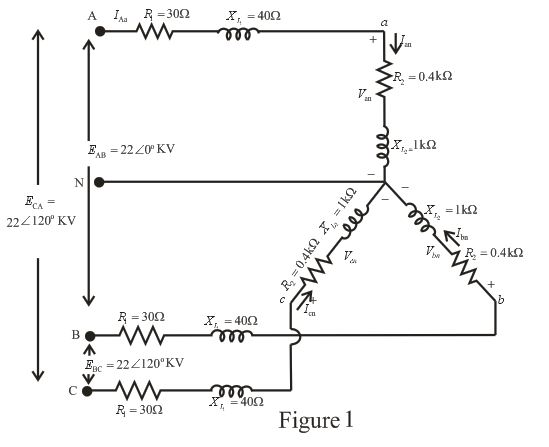
Expert Solution & Answer
Want to see the full answer?
Check out a sample textbook solution
Students have asked these similar questions
Solve for the voltage drop in the lines:
For Phase A, B and C.
Using Kirchhoff’s Law, determine the load currents (IA, IB, IC, ID, IE, IF, and IG).
Use Millman’s theorem and determine the magnitude of the neutral displacement voltage,(Vsn) in the phasor form.
Use Millman’s theorem and determine the phase voltage (Vbs) of the load in polar form.
Use Millman’s theorem and determine the phase voltage (Vbs) of the load in polar form.
Use Millman’s theorem and determine the current,(Ib) in phase b of the load in phasor form.
Use Millman’s theorem and determine the current,(Ib) in phase b of the load in phasor form.
Use Millman’s theorem and determine the reading on the wattmeter connected in line B of the circuit.
Chapter 24 Solutions
Introductory Circuit Analysis (13th Edition)
Ch. 24 - A balanced V load having a 10 resistance in each...Ch. 24 - Repeat Problem 1 if each phase impedance is...Ch. 24 - Repeat Problem 1 if each phase impedance is...Ch. 24 - The phase sequence for the Y-Y system in Fig....Ch. 24 - Repeat Problem 4 if each phase impedance are...Ch. 24 - Repeat Problem 4 if each phase impedance is...Ch. 24 - For the system in Fig. 24.43, find the magnitude...Ch. 24 - Computer the magnitude of the voltage EAB for the...Ch. 24 - For the Y-Y system in Fig. 24.45: a. Find the...Ch. 24 - For the Y-Y system of Fig. 24.46 the impedance of...
Ch. 24 - A balanced load having a 20 resistance in each...Ch. 24 - Repeat Problem 11 if each phase impedance is...Ch. 24 - Repeat Problem 11 if each phase impedance is...Ch. 24 - The phase sequence for the Y- system in Fig....Ch. 24 - Repeat Problem 14 if each phase impedance is...Ch. 24 - Repeat Problem 14 if each phase impedance are...Ch. 24 - Prob. 17PCh. 24 - For the connected load in Fig. 24.49: a. Find the...Ch. 24 - A balanced V load having a 30 resistance in each...Ch. 24 - Repeat Problem 19 if each phase impedance is...Ch. 24 - Prob. 21PCh. 24 - Prob. 22PCh. 24 - Prob. 23PCh. 24 - Repeat Problem 22 if each phase impedance is...Ch. 24 - Prob. 25PCh. 24 - Prob. 26PCh. 24 - Prob. 27PCh. 24 - The phase sequence for the - system in Fig....Ch. 24 - Repeat Problem 28 if each phase impedance is...Ch. 24 - Repeat Problem 28 if each phase impedance is...Ch. 24 - Prob. 31PCh. 24 - Prob. 32PCh. 24 - Prob. 33PCh. 24 - Find the total watts, volt-amperes reactive,...Ch. 24 - Prob. 35PCh. 24 - Find the total watts, volt-amperes reactive,...Ch. 24 - Find the total watts, volt-amperes reactive,...Ch. 24 - Prob. 38PCh. 24 - Prob. 39PCh. 24 - Find the total watts, volt-amperes reactive,...Ch. 24 - A balanced, three-phase, -connected load has a...Ch. 24 - A balanced, three-phase, Y-connected load has a...Ch. 24 - Find the total watts, volt-amperes reactive,...Ch. 24 - The Y-Y system in Fig. 24.53 has a balanced load...Ch. 24 - Prob. 45PCh. 24 - Prob. 46PCh. 24 - Repeat Problem 46 for the network in Fig. 24.47.Ch. 24 - For the three-wire system in Fig. 24.55, properly...Ch. 24 - Sketch three different ways that two wattmeters...Ch. 24 - For the Y- system in Fig. 24.56: Determine the...Ch. 24 - For the system in Fig. 24.57: Calculate the...Ch. 24 - For the three-phase, three-wire system in Fig....
Knowledge Booster


Learn more about
Need a deep-dive on the concept behind this application? Look no further. Learn more about this topic, electrical-engineering and related others by exploring similar questions and additional content below.Similar questions
- Need to find the line current and the phase currentarrow_forwardQuestion 4 The phase currents in a delta-connected three-phase load are as follows: between the red and yellow lines, 30 A at p.f. 0.707 leading; between the yellow and blue lines, 20 A at unity p.f.; between the blue and red lines, 25 A at p.f. 0.866 lagging. Calculate the line currents. Round your currents to one decimal place and your phase-angles to the nearest whole number.arrow_forward1. What is the main direct cause of reactive power in AC system? A. Resistance of transmission lines B. Inductance and capacitance in the loads C. Ideal transformer connected in the system D. Power produced by generator 2. "Reactive power in a system is dissipated generally as thermal energy?" A. TRUE B. FALSE 3. Which of the following statements are correct for three phase circuit: A. Sum of all the three phase currents is zero in unbalanced network B. Total power transfer to load is constant with time C. Neutral conductor is same size in terms of material used as in single phase conductors D. Net apparent power consumed is equal to real powerarrow_forward
- The input power to a 3-phase load is measured as 16kW. If the line current and power factor of the load are 21 A and 0.8 , then the value of line voltage is The field winding of DC. generator has capable of carrying the full-load current and it is usually made few turns of heavy gauge wire. separately excited Compound Shunt O Seriesarrow_forwardCalculate the amplitude of the line voltage per phase at the loadarrow_forwardIn Smith chart, if the value of the normalized load impedance ZLn is (3+jO), then the value of VSWR is: * 3 O 6 О 12 O 9arrow_forward
- Q2: A single-phase transmission line consisting of two conductors, the radius of each conductor is 0.4 cm, the distance between the conductors is three and half meters and the height above ground is eight meter. The capacitance in µF/km without effect -1 of ground is إجابتك The capacitance in µF/km with effect of -2 ground isarrow_forwardThe actual power flow on the transmission line is 1.25 pu and the voltage at both busbars is 1.0 pu. The system frequency is 60 Hz. The power flow is estimated using the phase difference between busbars 1 and 2, that is using ol -2. The actual value of ol -2=38.6822 deg. The measurement of the phase angle ol has a time stamp error of 0.1 ms and that of the phase angle 92 is 0.2ms. Calculate the error in the estimated power flow. Bus 1 Bus 2 PMU I j0.5 V= 1.0 PMU 2 V;= 1.0arrow_forwardPhase sequence in a balanced three phase system is RYB, if Y reaches maximum at 210°, then B reaches maximum atarrow_forward
- In Oman, the standard voltage of a single phase A.C. supply is of tion ON MS team link Jump to... rcharrow_forwardUse Kirchhoff’s Law to determine currents iA, iB, and iL.arrow_forwardIn a balanced system, the phasor sum of the line-to-line voltages and the phasor sum of the line-to-neutral voltages are always equal to zero. (a) False (b) Truearrow_forward
arrow_back_ios
SEE MORE QUESTIONS
arrow_forward_ios
Recommended textbooks for you
 Power System Analysis and Design (MindTap Course ...Electrical EngineeringISBN:9781305632134Author:J. Duncan Glover, Thomas Overbye, Mulukutla S. SarmaPublisher:Cengage Learning
Power System Analysis and Design (MindTap Course ...
Electrical Engineering
ISBN:9781305632134
Author:J. Duncan Glover, Thomas Overbye, Mulukutla S. Sarma
Publisher:Cengage Learning
How do Electric Transmission Lines Work?; Author: Practical Engineering;https://www.youtube.com/watch?v=qjY31x0m3d8;License: Standard Youtube License