
Introductory Circuit Analysis (13th Edition)
13th Edition
ISBN: 9780133923605
Author: Robert L. Boylestad
Publisher: PEARSON
expand_more
expand_more
format_list_bulleted
Concept explainers
Videos
Textbook Question
Chapter 24, Problem 28P
The phase sequence for the
a. Find the angles
b. Find the voltage across each phase impedance in phasor form.
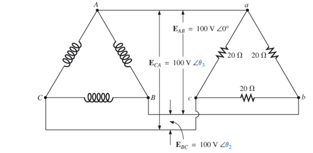
c. Draw the phasor diagram of the voltages found in part (b), and show that their phasor sum is zero around the close loop of the
d. Find the current through each phase impedance in phasor form.
e. Find the magnitude of the line currents.
Expert Solution & Answer
Want to see the full answer?
Check out a sample textbook solution
Students have asked these similar questions
1. Two impedances, Z1 =5230• ohms and Z2 = 10445• ohms, draw a current of 3.36 A when connected in series
to a certain a.c. supply. Determine (a) the supply voltage, (b) the phase angle between the voltage and current,
(c) the p.d. across Z1 and (d) the p.d. across Z2
Three Impedances each of (8 - j24)2 are
connected in mesh across a three-phase
420V ac supply. Determine the phase
current, line current, active power, reactive
power drawn from supply. Also draw the
Phasor diagram for the mesh connection and
marks the Line current ,phase current line
voltage and phase angle between phase
current and pahse voltage.
phase current (Ip)
Line current
real power
reactive power
In matlab, To obtain voltage and current waveforms
from transmission line which tool can be used
O a. voltage measurement
O b. Three-phase VI measurment
c. Series RLC branch
O d. Parallel RLC load
Chapter 24 Solutions
Introductory Circuit Analysis (13th Edition)
Ch. 24 - A balanced V load having a 10 resistance in each...Ch. 24 - Repeat Problem 1 if each phase impedance is...Ch. 24 - Repeat Problem 1 if each phase impedance is...Ch. 24 - The phase sequence for the Y-Y system in Fig....Ch. 24 - Repeat Problem 4 if each phase impedance are...Ch. 24 - Repeat Problem 4 if each phase impedance is...Ch. 24 - For the system in Fig. 24.43, find the magnitude...Ch. 24 - Computer the magnitude of the voltage EAB for the...Ch. 24 - For the Y-Y system in Fig. 24.45: a. Find the...Ch. 24 - For the Y-Y system of Fig. 24.46 the impedance of...
Ch. 24 - A balanced load having a 20 resistance in each...Ch. 24 - Repeat Problem 11 if each phase impedance is...Ch. 24 - Repeat Problem 11 if each phase impedance is...Ch. 24 - The phase sequence for the Y- system in Fig....Ch. 24 - Repeat Problem 14 if each phase impedance is...Ch. 24 - Repeat Problem 14 if each phase impedance are...Ch. 24 - Prob. 17PCh. 24 - For the connected load in Fig. 24.49: a. Find the...Ch. 24 - A balanced V load having a 30 resistance in each...Ch. 24 - Repeat Problem 19 if each phase impedance is...Ch. 24 - Prob. 21PCh. 24 - Prob. 22PCh. 24 - Prob. 23PCh. 24 - Repeat Problem 22 if each phase impedance is...Ch. 24 - Prob. 25PCh. 24 - Prob. 26PCh. 24 - Prob. 27PCh. 24 - The phase sequence for the - system in Fig....Ch. 24 - Repeat Problem 28 if each phase impedance is...Ch. 24 - Repeat Problem 28 if each phase impedance is...Ch. 24 - Prob. 31PCh. 24 - Prob. 32PCh. 24 - Prob. 33PCh. 24 - Find the total watts, volt-amperes reactive,...Ch. 24 - Prob. 35PCh. 24 - Find the total watts, volt-amperes reactive,...Ch. 24 - Find the total watts, volt-amperes reactive,...Ch. 24 - Prob. 38PCh. 24 - Prob. 39PCh. 24 - Find the total watts, volt-amperes reactive,...Ch. 24 - A balanced, three-phase, -connected load has a...Ch. 24 - A balanced, three-phase, Y-connected load has a...Ch. 24 - Find the total watts, volt-amperes reactive,...Ch. 24 - The Y-Y system in Fig. 24.53 has a balanced load...Ch. 24 - Prob. 45PCh. 24 - Prob. 46PCh. 24 - Repeat Problem 46 for the network in Fig. 24.47.Ch. 24 - For the three-wire system in Fig. 24.55, properly...Ch. 24 - Sketch three different ways that two wattmeters...Ch. 24 - For the Y- system in Fig. 24.56: Determine the...Ch. 24 - For the system in Fig. 24.57: Calculate the...Ch. 24 - For the three-phase, three-wire system in Fig....
Knowledge Booster


Learn more about
Need a deep-dive on the concept behind this application? Look no further. Learn more about this topic, electrical-engineering and related others by exploring similar questions and additional content below.Similar questions
- c) Drive the expression for maximum phase leads of m given network V. in R₁ min C₁ wwww R2arrow_forwardQ16 Complete the answer: Phase sequence in a balanced three phase system is RBY, if B reaches maximum at 210°, then Y reaches maximum at ................ degree.arrow_forwardA star connected three phase alternator supplies power to a delta connected resistive load. The alternator has a line voltage of 480V. Each resistor of delta load has 8 ohm of resistance. Find the following values. Line voltage of the load (VL(load)) Phase voltage of the load (VP(load)) Phase current of the load (IP(load)) Line current delivered by the alternator (IL(alt)) Phase current of the alternator (IP(Alt)) Phase voltage of the alternator (VP(Alt)) True powerarrow_forward
- A 60Hz, single-phase source with V=27730 volts is applied to a circuit element. (a) Determine the instantaneous source voltage. Also determine the phasor and instantaneous currents entering the positive terminal if the circuit element is (b) a 20 resistor. (C) a 10mH inductor, and (d) a capacitor with 25 reactance.arrow_forward1) What is the phase angle between the phases in an ideal 3-phase system?arrow_forward1. What is the main direct cause of reactive power in AC system? A. Resistance of transmission lines B. Inductance and capacitance in the loads C. Ideal transformer connected in the system D. Power produced by generator 2. "Reactive power in a system is dissipated generally as thermal energy?" A. TRUE B. FALSE 3. Which of the following statements are correct for three phase circuit: A. Sum of all the three phase currents is zero in unbalanced network B. Total power transfer to load is constant with time C. Neutral conductor is same size in terms of material used as in single phase conductors D. Net apparent power consumed is equal to real powerarrow_forward
- Use Millman’s theorem and determine the magnitude of the neutral displacement voltage,(Vsn) in the phasor form. Use Millman’s theorem and determine the phase voltage (Vbs) of the load in polar form. Use Millman’s theorem and determine the phase voltage (Vbs) of the load in polar form. Use Millman’s theorem and determine the current,(Ib) in phase b of the load in phasor form. Use Millman’s theorem and determine the current,(Ib) in phase b of the load in phasor form. Use Millman’s theorem and determine the reading on the wattmeter connected in line B of the circuit.arrow_forward1. Find the current and voltages Vr,Vl and Vc in phasor form. 2. Verify the kirchoffs volatage law around the closed loop. 3. Find the power factor of the circuit and indicate whether it os leading or laggingarrow_forward13. In parallel-connected ac circuit, the total current though the circuit is always equal to the phasor sum of the individual current though each element. True False 14. In a R-C parallel circuit, R=10 ohms and Xc=10 ohms, the applied voltage is leading to the circuit total current by 45 degrees (assumed applied voltage is the reference). True False 15. In a R-C series circuit, applied voltage is in phase with the total current. True Falsearrow_forward
- The values of the elements for the given circuit are given below.What is the maximum average power that can be transferred to the ZL load?R1 = 400 OhmsL = 500j OhmsR2 = 100 Ohmsarrow_forwardQ.2 For unbalanced system each phase is different from other and neutral current depends on phase currents. Compute sequential components of the given phase currents. 1. Ia 1.6 2 30 2. Ib 1.0 Z170 3. Ic= 0.9 150arrow_forwardA 415 V, 55 Hz 3-phase supply is connected to a 3- phase star connected balanced R-L load each of resistance 14 ohm and impedance 82 ohm. Find the value of inductance in each phase. 41.00 80.80 0.23 8.25arrow_forward
arrow_back_ios
SEE MORE QUESTIONS
arrow_forward_ios
Recommended textbooks for you
 Power System Analysis and Design (MindTap Course ...Electrical EngineeringISBN:9781305632134Author:J. Duncan Glover, Thomas Overbye, Mulukutla S. SarmaPublisher:Cengage Learning
Power System Analysis and Design (MindTap Course ...
Electrical Engineering
ISBN:9781305632134
Author:J. Duncan Glover, Thomas Overbye, Mulukutla S. Sarma
Publisher:Cengage Learning
Fault Analysis in Power Systems part 1a; Author: GeneralPAC: Power System Tutorials;https://www.youtube.com/watch?v=g8itg4MOjok;License: Standard youtube license