
Mechanics of Materials, 7th Edition
7th Edition
ISBN: 9780073398235
Author: Ferdinand P. Beer, E. Russell Johnston Jr., John T. DeWolf, David F. Mazurek
Publisher: McGraw-Hill Education
expand_more
expand_more
format_list_bulleted
Concept explainers
Videos
Textbook Question
Chapter 2.3, Problem 45P
The rigid bar ABC is suspended from three wines of the same material. The cross-sectional area of the wire at B is equal to half of the cross-sectional area of the wires at A and C. Determine the tension in each wire caused by the load P shown.
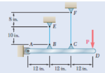
Fig. P2.45
Expert Solution & Answer
Want to see the full answer?
Check out a sample textbook solution
Students have asked these similar questions
2.18 The rigid bar AB is supported by two rods made of the same material. If the
bar is horizontal before the load P is applied, find the distance x that locates the
position where P must act if the bar is to remain horizontal. Neglect the weight of
bar AB.
L=3 ft
A=0.2 in.?
L=2 ft
A = 0.4 in.?
A.
10 ft
FIG. P2.18
W
FIG. P2.102
EXERCISE 4.2
1. Three long parallel wires equal in length are supporting a rigid bar connected at their bottoms as
shown in Fig. 4.15. If the cross-sectional area of each wire is 100 mm“, calculate the stresses in
each wire. Take E, = 100 GPa and E, = 200 GPa.
[Ans. O, = 25 MPa ; o, = 50 MPa]
10 kN
220 kN
Fig. 4.15
Fig. 4.16
2. Three wires made of copper, zinc and aluminium are of equal lengths and have cross-sectional
areas of 100, 150 and 200 square mm respectively. They are rigidly connected at their ends as
shown in Fig. 4.16. If this compound member is subjected to a longitudinal pull of 220 kN,
estimate the load carried on each wire. Take E = 130 GPa, E, = 100 GPa and E, = 80 GPa.
[Ans. Pe= 65 kN, P,= 75 kN, P= 80 kN]
3. Two steel rods and one copper rod each of 20 mm diameter together support a load of 50 kN as
shown in Fig.4.17. Find the stresses in each rod. Take E for steel and copper as 200 GPa and
[Ans. o. = 39.8 MPa ; o, = 59.7 MPa]
100 GPa respectively.
60 I Strength of…
Chapter 2 Solutions
Mechanics of Materials, 7th Edition
Ch. 2.1 - A nylon thread is subjected to a 8.5-N tension...Ch. 2.1 - A 4.8-ft-long steel wire of 14 -in.-diameter is...Ch. 2.1 - An 18-m-long steel wire of 5-mm diameter is to be...Ch. 2.1 - Two gage marks are placed exactly 250 mm apart on...Ch. 2.1 - An aluminum pipe must not stretch more than 0.05...Ch. 2.1 - A control rod made of yellow brass must not...Ch. 2.1 - A steel control rod is 5.5 ft long and must not...Ch. 2.1 - A cast-iron tube is used to support a compressive...Ch. 2.1 - A 4-m-long steel rod must not stretch more than 3...Ch. 2.1 - A nylon thread is to be subjected to a 10-N...
Ch. 2.1 - A block of 10-in. length and 1.8 1.6-in. cross...Ch. 2.1 - A square yellow-brass bar must not stretch more...Ch. 2.1 - Rod BD is made of steel (E = 29 106 psi) and is...Ch. 2.1 - The 4-mm-diameter cable BC is made of a steel with...Ch. 2.1 - A single axial load of magnitude P = 15 kips is...Ch. 2.1 - A 250-mm-long aluminum tube (E = 70 GPa) of 36-mm...Ch. 2.1 - The specimen shown has been cut from a...Ch. 2.1 - The brass tube AB (E = 105 GPa) has a...Ch. 2.1 - Both portions of the rod ABC are made of an...Ch. 2.1 - The rod ABC is made of an aluminum for which E =...Ch. 2.1 - For the steel truss (E = 200 GPa) and loading...Ch. 2.1 - For the steel truss (E = 29 106 psi) and loading...Ch. 2.1 - Members AB and BC are made of steel (E = 29 106...Ch. 2.1 - The steel frame (E = 200 GPa) shown has a diagonal...Ch. 2.1 - Link BD is made of brass (E = 105 GPa) and has a...Ch. 2.1 - Members ABC and DEF are joined with steel links (E...Ch. 2.1 - Each of the links AB and CD is made of aluminum (E...Ch. 2.1 - The length of the 332-in.-diameter steel wire CD...Ch. 2.1 - A homogenous cable of length L and uniform cross...Ch. 2.1 - The vertical load P is applied at the center A of...Ch. 2.1 - Denoting by the "engineering strain'' in a...Ch. 2.1 - The volume of a tensile specimen is essentially...Ch. 2.3 - An axial centric force of magnitude P = 450 kN is...Ch. 2.3 - An axial centric force of magnitude P = 450 kN is...Ch. 2.3 - The 4.5-ft concrete post is reinforced with six...Ch. 2.3 - The 4.5-ft concrete post is reinforced with six...Ch. 2.3 - An axial force of 200 kW is applied to the...Ch. 2.3 - The length of the assembly shown decreases by 0.40...Ch. 2.3 - A polystyrene rod consisting of two cylindrical...Ch. 2.3 - Three steel rods (E = 29 106 psi) support an...Ch. 2.3 - Fig. P2.41 2.41 Two cylindrical rods, one of steel...Ch. 2.3 - Solve Prob. 2.41, assuming that rod AC is made of...Ch. 2.3 - Each of the rods BD and CE is made of brass (E =...Ch. 2.3 - The rigid bar AD is supported by two steel wires...Ch. 2.3 - The rigid bar ABC is suspended from three wines of...Ch. 2.3 - The rigid bar AD is supported by two steel wires...Ch. 2.3 - The aluminum shell is fully bonded to the brass...Ch. 2.3 - The aluminum shell is fully bonded to the brass...Ch. 2.3 - The brass shell (b = 11.6 10-6/F) is fully bonded...Ch. 2.3 - The concrete post (Ec = 3.6 106) psi and c = 5.5 ...Ch. 2.3 - A rod consisting of two cylindrical portions AB...Ch. 2.3 - A rod consisting of two cylindrical portions AB...Ch. 2.3 - Fig. P2.52 2.52 A rod consisting of two...Ch. 2.3 - The steel rails of a railroad (rack (Es = 200GPa,...Ch. 2.3 - Two steel bars (Es = 200 GPa and s = 11.7 10-6/C)...Ch. 2.3 - Determine the maximum load P that can be applied...Ch. 2.3 - An aluminum rod (Ea = 70 GPa, a = 23.6 10-6/C)...Ch. 2.3 - Knowing that a 0.02-in. gap exists when the...Ch. 2.3 - Determine (a) the compressive force in the bars...Ch. 2.3 - At room temperature (20C) a 0.5-mm gap exists...Ch. 2.9 - A standard tension test is used to determine the...Ch. 2.9 - A 2-m length of an aluminum pipe of 240-nun outer...Ch. 2.9 - A line of slope 4:10 has been scribed on a...Ch. 2.9 - A 2.75-kN tensile load is applied to a test coupon...Ch. 2.9 - Fig. P2.65 2.65 In a standard tensile test a steel...Ch. 2.9 - The change in diameter of a large steel bolt is...Ch. 2.9 - The brass rod AD is fitted with a jacket that is...Ch. 2.9 - A fabric used in air-inflated structures is...Ch. 2.9 - A 1-in. square was scribed on the side of a large...Ch. 2.9 - The block shown is made of a magnesium alloy for...Ch. 2.9 - The homogeneous plate ABCD is subjected to a...Ch. 2.9 - For a member under axial loading, express the...Ch. 2.9 - In many situations it is known that the normal...Ch. 2.9 - In many situations physical constraints prevent...Ch. 2.9 - The plastic block shown is bonded to a rigid...Ch. 2.9 - The plastic block shown is bonded to a rigid...Ch. 2.9 - Two blocks of rubber with a modulus of rigidity G...Ch. 2.9 - Fig. P2.77 and P2.78 2.78 Two blocks of rubber...Ch. 2.9 - An elastomeric bearing (G = 130 psi) is used to...Ch. 2.9 - 2.80 For the elastomeric bearing In Prob. 2.79...Ch. 2.9 - A vibration isolation unit consists of two blocks...Ch. 2.9 - Prob. 82PCh. 2.9 - Prob. 83PCh. 2.9 - Prob. 84PCh. 2.9 - Prob. 85PCh. 2.9 - A 2.75-kN tensile load is applied to a test coupon...Ch. 2.9 - A vibration isolation support consists of a rod A...Ch. 2.9 - Prob. 88PCh. 2.9 - Prob. 89PCh. 2.9 - Show that for any given material, the ratio G/E of...Ch. 2.9 - Prob. 91PCh. 2.9 - Prob. 92PCh. 2.13 - Knowing that, for the plate shown, the allowable...Ch. 2.13 - Knowing that P = 38 kN, determine the maximum...Ch. 2.13 - A hole is to be drilled in the plate at A. The...Ch. 2.13 - Fig. P2.95 and P2.96 2.96 (a) For P = 13 kips and...Ch. 2.13 - 2.97 Knowing that the hole has a diameter of 9 mm,...Ch. 2.13 - For P = 100 kN, determine the minimum plate...Ch. 2.13 - Prob. 99PCh. 2.13 - A centric axial force is applied to the steel bar...Ch. 2.13 - The cylindrical rod AB has a length L = 5 ft and a...Ch. 2.13 - Fig. P2.101 and P.102 2.102 The cylindrical rod AB...Ch. 2.13 - Rod AB is made of a mild steel that is assumed to...Ch. 2.13 - Prob. 104PCh. 2.13 - Rod ABC consists of two cylindrical portions and...Ch. 2.13 - Prob. 106PCh. 2.13 - Prob. 107PCh. 2.13 - Prob. 108PCh. 2.13 - Each cable has a cross-sectional area of 100 mm2...Ch. 2.13 - Prob. 110PCh. 2.13 - Two tempered-steel bars, each 316 in. thick, are...Ch. 2.13 - Prob. 112PCh. 2.13 - Prob. 113PCh. 2.13 - Prob. 114PCh. 2.13 - Prob. 115PCh. 2.13 - Prob. 116PCh. 2.13 - Prob. 117PCh. 2.13 - Prob. 118PCh. 2.13 - Prob. 119PCh. 2.13 - For the composite bar in Prob. 2.111, determine...Ch. 2.13 - Prob. 121PCh. 2.13 - Bar AB has a cross-sectional area of 1200 mm2 and...Ch. 2.13 - Bar AB has a cross-sectional area of 1200 mm2 and...Ch. 2 - The uniform wire ABC, of unstretched length 2l, is...Ch. 2 - The aluminum rod ABC (E = 10.1 106 psi), which...Ch. 2 - Two solid cylindrical rods are joined at B and...Ch. 2 - Prob. 127RPCh. 2 - Prob. 128RPCh. 2 - Prob. 129RPCh. 2 - A 4-ft concrete post is reinforced with four steel...Ch. 2 - The steel rods BE and CD each have a 16-mm...Ch. 2 - Prob. 132RPCh. 2 - Prob. 133RPCh. 2 - The aluminum test specimen shown is subjected to...Ch. 2 - Prob. 135RP
Knowledge Booster


Learn more about
Need a deep-dive on the concept behind this application? Look no further. Learn more about this topic, mechanical-engineering and related others by exploring similar questions and additional content below.Similar questions
- 2. A load of 100 lbs is hung from the middle of a rope, which is stretched between two rigid walls 30 ft apart. Due to the load, the rope sags 4 feet in the middle. Determine the tension in the rope.arrow_forward2.1 (A). A power transmission cable consists of ten copper wires each of 1.6 mm diameter Surrounding three steel wires each of 3 mm diameter. Determine the combined E for the compound cable and hence determine the extension of a 30 m length of the cable when it is being laid with a tension of 2 kN. For steel, E = 200 GN/m?; for copper, E = 100 GN/m?.arrow_forward2.5 m 3.5 m -4.0 m Fig. P2.13arrow_forward
- 6. 320 lb The frame ACD is supported by ball-and-socket joints at A and D and by a cable that passes through a ring at B and is attached to hooks at G and H. Knowing that the frame supports at point C a load of magnitude P= 268 N, determine the tension in the cable. 0.925 m 0.35 m 0.5 m B 0.5 m 3 of 3 0.875 m P H 0.75 m 0.75 m xarrow_forwardP 1 mm 375 mm C Fig. P2.16arrow_forwardQuestion The rigid bar ABCD is supported by a pin at B and restrained by identical steel bars at C and D, each of area 250 mm². If the temperature is increased by 80°C, determine the force P that will cause the bar at C to be stress-free. Use E = 200 GPa and a = 12 × 10-6/°C. 3 m 0.8 m -0.6 m Co D A FIG. P2.89arrow_forward
- (a) To determine the tension developed in cable AB (b) To determine the tension developed in cable AC (c) To determine the force developed along the z axis of the antenna tower AE Express your answer in pounds to three significant figures. only HANDWRITTEN answer needed ( NOT TYPED)arrow_forward2.43 A steel tube (E = 29 x 106 psi) with a 14-in. outer diameter and a -in. thickness is placed in a vise that is adjusted so that its jaws just touch the ends of the tube without exerting any pressure on them. The two forces shown are then applied to the tube. After these forces are applied, the vise is adjusted to decrease the distance between its jaws by 0.008 in. Determine (a) the forces exerted by the vise on the tube at A and D, (b) the change in length of the portion BC of the tube. Fig. P2.43 -3 in.3 in.3 in. - 3- D 8 kips B 6 kipsarrow_forward3.112 Pulleys A and B are mounted on bracket CDEF. The tension on each side of the two belts is as shown. Replace the four forces with a single equivalent force, and determine where its line of action intersects the bottom edge of the bracket. Fig. P3.112 A 2 in. LE F 1 in. r = 2 in. r= 1 in. 6 in.- 120 lb A -6 in. 160 lb B D E 4 in. 210 lb $25° -150 lb $25°arrow_forward
- 2.13 A steel plate, which is 1.5 m by 1.5 m and 30 mm thick, is lifted by four cables attached to its corners that meet at a point that is 2 m above the plate. Determine the required cross-sectional area of the cables if the stress in them is not to exceed 20 MPa. Steel plate Prob. 2.13 Cablesarrow_forwardQuestion The rigid bar ABCD is supported by a pin at B and restrained by identical steel bars at C and D, each of area 250 mm?. If the temperature is increased by 80°C, determine the force P that will cause the bar at C to be stress-free. Use E = 200 GPa and a = 12 x 10-6/°C. 3 m 0.8 m -0.6 m A B Co FIG. P2.89arrow_forwardA transmission tower is held by three guy wires attached to a pin at A and anchored by bolts at B, C, and D. If the tension in wire AC is 413 Ib, determine the vertical force P exerted by the tower on the pin at A. 100 ft D 20 ft 25 ft B 74 ft 20 ft 60 ft `18 ft The vertical force P exerted by the tower on the pin at A is Ib.arrow_forward
arrow_back_ios
SEE MORE QUESTIONS
arrow_forward_ios
Recommended textbooks for you
 Elements Of ElectromagneticsMechanical EngineeringISBN:9780190698614Author:Sadiku, Matthew N. O.Publisher:Oxford University Press
 Mechanics of Materials (10th Edition)Mechanical EngineeringISBN:9780134319650Author:Russell C. HibbelerPublisher:PEARSON
 Thermodynamics: An Engineering ApproachMechanical EngineeringISBN:9781259822674Author:Yunus A. Cengel Dr., Michael A. BolesPublisher:McGraw-Hill Education
 Control Systems EngineeringMechanical EngineeringISBN:9781118170519Author:Norman S. NisePublisher:WILEY
 Mechanics of Materials (MindTap Course List)Mechanical EngineeringISBN:9781337093347Author:Barry J. Goodno, James M. GerePublisher:Cengage Learning
 Engineering Mechanics: StaticsMechanical EngineeringISBN:9781118807330Author:James L. Meriam, L. G. Kraige, J. N. BoltonPublisher:WILEY
Elements Of Electromagnetics
Mechanical Engineering
ISBN:9780190698614
Author:Sadiku, Matthew N. O.
Publisher:Oxford University Press
Mechanics of Materials (10th Edition)
Mechanical Engineering
ISBN:9780134319650
Author:Russell C. Hibbeler
Publisher:PEARSON
Thermodynamics: An Engineering Approach
Mechanical Engineering
ISBN:9781259822674
Author:Yunus A. Cengel Dr., Michael A. Boles
Publisher:McGraw-Hill Education
Control Systems Engineering
Mechanical Engineering
ISBN:9781118170519
Author:Norman S. Nise
Publisher:WILEY
Mechanics of Materials (MindTap Course List)
Mechanical Engineering
ISBN:9781337093347
Author:Barry J. Goodno, James M. Gere
Publisher:Cengage Learning
Engineering Mechanics: Statics
Mechanical Engineering
ISBN:9781118807330
Author:James L. Meriam, L. G. Kraige, J. N. Bolton
Publisher:WILEY
Types Of loads - Engineering Mechanics | Abhishek Explained; Author: Prime Course;https://www.youtube.com/watch?v=4JVoL9wb5yM;License: Standard YouTube License, CC-BY