
Videos
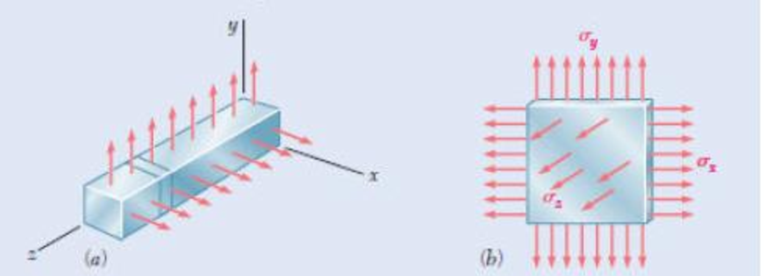
In many situations physical constraints prevent strain from occurring in a given direction. For example, ∈z = 0 in the case shown, where longitudinal movement of the long prism is prevented at every point. Plane sections perpendicular to the longitudinal axis remain plane and the same distance apart. Show that for this situation, which is known as plane strain, we can express ϭz, ∈x and ∈y. as follows:
Want to see the full answer?
Check out a sample textbook solution
Chapter 2 Solutions
Mechanics of Materials, 7th Edition


- The state of plane strain on an element is represented by the following components: Ex =D340 x 10-6, ɛ, = , yxy Ey =D110 x 10-6, 3D180 x10-6 ху Draw Mohr's circle to represent this state of strain. Use Mohrs circle to obtain the principal strains and principal plane.arrow_forwardDetermine the transverse strain in the x axis of the solid subjected to longitudinal tension. 4 cm 1 cm 6x10³ N 2 cm μ = 0,28 E=1,4x10" N/m² 6x10³ Narrow_forward(b) A differential element on the bracket as shown in Figure Q1 is subjected to plane strain that has the following components: ex = 150µ, ey = 200μ , γχν = -700μ. By using the strain transformation equations, determine:- The equivalent in-plane strains on an element oriented at an angle 0 = 60° counterclockwise from the original position. (ii) Sketch the deformed element within the x' – y' plane due to these strains. (iii) The stresses on the oriented planes in (i) where the value of elasticity, E = 200 GPa and Poisson's ratio, v = 0.32. (iv) Give your comments on those stresses in (iii) in terms of elastic limit/failure if the material's yield strength in tension/compression is 250 MPa and in shear is 90 MPa.arrow_forward
- 1. A circular aluminium tube of length L = 400 mm is loaded in compression by the force P. The outside and inside diameters are 60 mm and 50 mm, respectively. A strain gage is placed on the outside of the bar to measure normal strains in the longitudinal direction. 1.1 If the measured strain is ε = 550 x 10-6, what is the shortening δ of the bar? 1.2 If the compressive stress in the bar is intended to be 40 MPa, what should be the load P? 2. A cylindrical vessel has an internal diameter of 2 m. It is made of 15 mm thick plate. The efficiency of the longitudinal and circumferential joints are 80 % and 60 % respectively. If the ultimate tensile stress for the material is 500 MPa and the factor of safety is 6, determine the safe internal pressure to which the vessel may be subjected.arrow_forwardThe state of strain in a plane element is ex =-200 x 10-6, Ey = 0, and yxy = 75 × 10-6 , as shown below. Determine the equivalent state of strain which represents (a) the principal strains (b) the maximum in-plane shear strain and the associated average normal strain. Specify the orientation of the corresponding elements for these states of strain with respect to the original element. y Yxy 2 dy Yxy FExdx dxarrow_forwardA 45° strain rosette was placed on the surface of a critical point on an engineering part. The following were measured: Ea = 400 μ C ли 45° mm mm 45° ли Gauge a was aligned with the x-axis. a. Determine Ex, Ey, Yxy b. Using Mohr's Circle, find the principal strains and the maximum shear strain at that point, and find the orientation of the principal planes from the given x-y axes. y ли & = 450 μ ஆ b a mm X mm & c = 500 μ y+ ос mm mm eb 10₂ Xarrow_forward
- In many situations physical constraints prevent strain from occurring in a given direction. For example, εz= 0 in the case shown, where longitudinal movement of the long prism is prevented at every point. Plane sections perpendicular to the longitudinal axis remain plane and the same distance apart. Show that for this situation, which is known as plane strain, we can express σz, εx, and εy as followsarrow_forwardQuestion 2 A 60° strain rosette is installed on the traction-free surface of a component with one of the strain gages aligned along the y-axis, as illustrated in Figure Q2. The gages show the following strain readings upon loading the structure: E, = 925 x10“ ; &, = 740 x10“ ; ɛ. = -555 ×106 (a) Determine the strains in the x-y directions and show the corresponding strain element. (b) Calculate the principal in-plane strains and the corresponding principal directions. Show the principal strain element. (c) Calculate the in-plane maximum shear strain and show the corresponding strain element. (d) If the structure is made of steel with elastic modulus and Poisson's ratio of 220 GPa and 0.30, respectively, calculate the principal stresses. Show the principal stress element. (e) Determine the normal strain in the n-direction. & Eaarrow_forward5 decimal places Determine the total strain (mm/mm) of a 2.64-m bar with a diameter of 21 mm subjected to a tensile force of 71 kN at a temperature increase of 49 C°. Consider the α=27.3 µm/mC° and E = 122 GPa.arrow_forward
- The state of strain in a plane element is Ex = -300 x 10-6 , Ey= 450 x 10-6, and Yxy = 275 x 10-6. (a) Use the strain transformation equations to determine the equivalent strain components on an element oriented at an angle of 0 = 30° counterclockwise from the original position. (b) Sketch the deformed element due to these strains within the x-y plane.arrow_forwardThe state of strain in a plane element is €x = -200 x 10-6 , Ey = 100 × 10-6 , and Yxy = 75 x 10-6 , as shown below. Determine the equivalent state of strain which represents (a) the principal strains (b) the maximum in-plane shear strain and the associated average normal strain. Specify the orientation of the corresponding elements for these states of strain with respect to the original element. y Eydy Yxy 2 dy Yxy FExdx 2 dxarrow_forwardA rectangular aluminum plate of uniform thickness has a strain gauge at the center. It is placed in a test rig which can apply a biaxial force system along the edges of the plate as shown below. If the measured strains are +0.0005 and +0.001 in the x and y directions respectively, a) Determine the corresponding stresses set up in the plate and the strain through the thickness, εz. Take E=72 GPa and ν=0.32. b) Construct the Mohr’s circle for the loaded plate. c) State the values of the principal stresses. d) Determine the maximum shearing stresses and the directions of the planes on which they occur.arrow_forward
 Elements Of ElectromagneticsMechanical EngineeringISBN:9780190698614Author:Sadiku, Matthew N. O.Publisher:Oxford University Press
 Mechanics of Materials (10th Edition)Mechanical EngineeringISBN:9780134319650Author:Russell C. HibbelerPublisher:PEARSON
 Thermodynamics: An Engineering ApproachMechanical EngineeringISBN:9781259822674Author:Yunus A. Cengel Dr., Michael A. BolesPublisher:McGraw-Hill Education
 Control Systems EngineeringMechanical EngineeringISBN:9781118170519Author:Norman S. NisePublisher:WILEY
 Mechanics of Materials (MindTap Course List)Mechanical EngineeringISBN:9781337093347Author:Barry J. Goodno, James M. GerePublisher:Cengage Learning
 Engineering Mechanics: StaticsMechanical EngineeringISBN:9781118807330Author:James L. Meriam, L. G. Kraige, J. N. BoltonPublisher:WILEY