
Mechanics of Materials, 7th Edition
7th Edition
ISBN: 9780073398235
Author: Ferdinand P. Beer, E. Russell Johnston Jr., John T. DeWolf, David F. Mazurek
Publisher: McGraw-Hill Education
expand_more
expand_more
format_list_bulleted
Concept explainers
Videos
Textbook Question
Chapter 2.9, Problem 80P
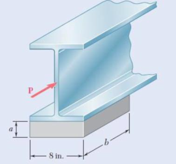
2.80 For the elastomeric bearing In Prob. 2.79 with b = 10 in. and a = 1 in., determine the shearing modulus G and the shear stress τ for a maximum lateral load P = 5 kips and a maximum displacement δ = 0.4 in.
2.79 An elastomeric bearing (G = 130 psi) is used to support a bridge girder as shown to provide flexibility during earthquakes. The beam must not displace more than
Expert Solution & Answer
Want to see the full answer?
Check out a sample textbook solution
Students have asked these similar questions
A rectangular steel block is 3 inches long in the x direction, 2 inches long in the y direction, and 4 inches long in the z direction. The block is subjected to a triaxial loading of three uniformly distributed forces as floows; 48 kips tension in the x directio, 60 kips compression in the y direction, and 54 kips tension in the z direction. If v = 0.30 and E = 29 x 106 psi, determine the single uniformly distributed load in the x direction that would produce the same deformation in the y direction as the original loading.
1.2 A steel rod of 30 mm diameter is enclosed centrally in a hollow copper tube of external
diameter 40 mm and 5 mm thick. The composite bar is then subjected to an axial pull of
45 kN. If the length of the compound rod is 150 mm, and the elasticity moduli are
Est = 200 GPa and Ecu= 100 GPa. determine:
1.2.1
The stresses in the rod and tube
1.2.2
The load carried by the rod and that carried by the tube
1.2.3
The elongation of the compound rod.
Problem 2
The mechanical system consists of two identical steel rods (A = 30 mm2, E = 200GPA,
a = 15x106/°C) and a "rigid" beam AC. The beam is supported by a smooth pin at
B. The nuts at A and C are initially tightened just enough to remove the slack,
leaving the two rods stress-free.
1- Determine the axial stresses induced in rods (1) and (2) if the temperature of
both rods is decreased by 60°C.
2- Determine the (small) angle 0 through which the beam AC would rotate due
to this temperature change.
-200 mm
80 mm
В
"Rigid"
(2) 250 mm
(1)
Chapter 2 Solutions
Mechanics of Materials, 7th Edition
Ch. 2.1 - A nylon thread is subjected to a 8.5-N tension...Ch. 2.1 - A 4.8-ft-long steel wire of 14 -in.-diameter is...Ch. 2.1 - An 18-m-long steel wire of 5-mm diameter is to be...Ch. 2.1 - Two gage marks are placed exactly 250 mm apart on...Ch. 2.1 - An aluminum pipe must not stretch more than 0.05...Ch. 2.1 - A control rod made of yellow brass must not...Ch. 2.1 - A steel control rod is 5.5 ft long and must not...Ch. 2.1 - A cast-iron tube is used to support a compressive...Ch. 2.1 - A 4-m-long steel rod must not stretch more than 3...Ch. 2.1 - A nylon thread is to be subjected to a 10-N...
Ch. 2.1 - A block of 10-in. length and 1.8 1.6-in. cross...Ch. 2.1 - A square yellow-brass bar must not stretch more...Ch. 2.1 - Rod BD is made of steel (E = 29 106 psi) and is...Ch. 2.1 - The 4-mm-diameter cable BC is made of a steel with...Ch. 2.1 - A single axial load of magnitude P = 15 kips is...Ch. 2.1 - A 250-mm-long aluminum tube (E = 70 GPa) of 36-mm...Ch. 2.1 - The specimen shown has been cut from a...Ch. 2.1 - The brass tube AB (E = 105 GPa) has a...Ch. 2.1 - Both portions of the rod ABC are made of an...Ch. 2.1 - The rod ABC is made of an aluminum for which E =...Ch. 2.1 - For the steel truss (E = 200 GPa) and loading...Ch. 2.1 - For the steel truss (E = 29 106 psi) and loading...Ch. 2.1 - Members AB and BC are made of steel (E = 29 106...Ch. 2.1 - The steel frame (E = 200 GPa) shown has a diagonal...Ch. 2.1 - Link BD is made of brass (E = 105 GPa) and has a...Ch. 2.1 - Members ABC and DEF are joined with steel links (E...Ch. 2.1 - Each of the links AB and CD is made of aluminum (E...Ch. 2.1 - The length of the 332-in.-diameter steel wire CD...Ch. 2.1 - A homogenous cable of length L and uniform cross...Ch. 2.1 - The vertical load P is applied at the center A of...Ch. 2.1 - Denoting by the "engineering strain'' in a...Ch. 2.1 - The volume of a tensile specimen is essentially...Ch. 2.3 - An axial centric force of magnitude P = 450 kN is...Ch. 2.3 - An axial centric force of magnitude P = 450 kN is...Ch. 2.3 - The 4.5-ft concrete post is reinforced with six...Ch. 2.3 - The 4.5-ft concrete post is reinforced with six...Ch. 2.3 - An axial force of 200 kW is applied to the...Ch. 2.3 - The length of the assembly shown decreases by 0.40...Ch. 2.3 - A polystyrene rod consisting of two cylindrical...Ch. 2.3 - Three steel rods (E = 29 106 psi) support an...Ch. 2.3 - Fig. P2.41 2.41 Two cylindrical rods, one of steel...Ch. 2.3 - Solve Prob. 2.41, assuming that rod AC is made of...Ch. 2.3 - Each of the rods BD and CE is made of brass (E =...Ch. 2.3 - The rigid bar AD is supported by two steel wires...Ch. 2.3 - The rigid bar ABC is suspended from three wines of...Ch. 2.3 - The rigid bar AD is supported by two steel wires...Ch. 2.3 - The aluminum shell is fully bonded to the brass...Ch. 2.3 - The aluminum shell is fully bonded to the brass...Ch. 2.3 - The brass shell (b = 11.6 10-6/F) is fully bonded...Ch. 2.3 - The concrete post (Ec = 3.6 106) psi and c = 5.5 ...Ch. 2.3 - A rod consisting of two cylindrical portions AB...Ch. 2.3 - A rod consisting of two cylindrical portions AB...Ch. 2.3 - Fig. P2.52 2.52 A rod consisting of two...Ch. 2.3 - The steel rails of a railroad (rack (Es = 200GPa,...Ch. 2.3 - Two steel bars (Es = 200 GPa and s = 11.7 10-6/C)...Ch. 2.3 - Determine the maximum load P that can be applied...Ch. 2.3 - An aluminum rod (Ea = 70 GPa, a = 23.6 10-6/C)...Ch. 2.3 - Knowing that a 0.02-in. gap exists when the...Ch. 2.3 - Determine (a) the compressive force in the bars...Ch. 2.3 - At room temperature (20C) a 0.5-mm gap exists...Ch. 2.9 - A standard tension test is used to determine the...Ch. 2.9 - A 2-m length of an aluminum pipe of 240-nun outer...Ch. 2.9 - A line of slope 4:10 has been scribed on a...Ch. 2.9 - A 2.75-kN tensile load is applied to a test coupon...Ch. 2.9 - Fig. P2.65 2.65 In a standard tensile test a steel...Ch. 2.9 - The change in diameter of a large steel bolt is...Ch. 2.9 - The brass rod AD is fitted with a jacket that is...Ch. 2.9 - A fabric used in air-inflated structures is...Ch. 2.9 - A 1-in. square was scribed on the side of a large...Ch. 2.9 - The block shown is made of a magnesium alloy for...Ch. 2.9 - The homogeneous plate ABCD is subjected to a...Ch. 2.9 - For a member under axial loading, express the...Ch. 2.9 - In many situations it is known that the normal...Ch. 2.9 - In many situations physical constraints prevent...Ch. 2.9 - The plastic block shown is bonded to a rigid...Ch. 2.9 - The plastic block shown is bonded to a rigid...Ch. 2.9 - Two blocks of rubber with a modulus of rigidity G...Ch. 2.9 - Fig. P2.77 and P2.78 2.78 Two blocks of rubber...Ch. 2.9 - An elastomeric bearing (G = 130 psi) is used to...Ch. 2.9 - 2.80 For the elastomeric bearing In Prob. 2.79...Ch. 2.9 - A vibration isolation unit consists of two blocks...Ch. 2.9 - Prob. 82PCh. 2.9 - Prob. 83PCh. 2.9 - Prob. 84PCh. 2.9 - Prob. 85PCh. 2.9 - A 2.75-kN tensile load is applied to a test coupon...Ch. 2.9 - A vibration isolation support consists of a rod A...Ch. 2.9 - Prob. 88PCh. 2.9 - Prob. 89PCh. 2.9 - Show that for any given material, the ratio G/E of...Ch. 2.9 - Prob. 91PCh. 2.9 - Prob. 92PCh. 2.13 - Knowing that, for the plate shown, the allowable...Ch. 2.13 - Knowing that P = 38 kN, determine the maximum...Ch. 2.13 - A hole is to be drilled in the plate at A. The...Ch. 2.13 - Fig. P2.95 and P2.96 2.96 (a) For P = 13 kips and...Ch. 2.13 - 2.97 Knowing that the hole has a diameter of 9 mm,...Ch. 2.13 - For P = 100 kN, determine the minimum plate...Ch. 2.13 - Prob. 99PCh. 2.13 - A centric axial force is applied to the steel bar...Ch. 2.13 - The cylindrical rod AB has a length L = 5 ft and a...Ch. 2.13 - Fig. P2.101 and P.102 2.102 The cylindrical rod AB...Ch. 2.13 - Rod AB is made of a mild steel that is assumed to...Ch. 2.13 - Prob. 104PCh. 2.13 - Rod ABC consists of two cylindrical portions and...Ch. 2.13 - Prob. 106PCh. 2.13 - Prob. 107PCh. 2.13 - Prob. 108PCh. 2.13 - Each cable has a cross-sectional area of 100 mm2...Ch. 2.13 - Prob. 110PCh. 2.13 - Two tempered-steel bars, each 316 in. thick, are...Ch. 2.13 - Prob. 112PCh. 2.13 - Prob. 113PCh. 2.13 - Prob. 114PCh. 2.13 - Prob. 115PCh. 2.13 - Prob. 116PCh. 2.13 - Prob. 117PCh. 2.13 - Prob. 118PCh. 2.13 - Prob. 119PCh. 2.13 - For the composite bar in Prob. 2.111, determine...Ch. 2.13 - Prob. 121PCh. 2.13 - Bar AB has a cross-sectional area of 1200 mm2 and...Ch. 2.13 - Bar AB has a cross-sectional area of 1200 mm2 and...Ch. 2 - The uniform wire ABC, of unstretched length 2l, is...Ch. 2 - The aluminum rod ABC (E = 10.1 106 psi), which...Ch. 2 - Two solid cylindrical rods are joined at B and...Ch. 2 - Prob. 127RPCh. 2 - Prob. 128RPCh. 2 - Prob. 129RPCh. 2 - A 4-ft concrete post is reinforced with four steel...Ch. 2 - The steel rods BE and CD each have a 16-mm...Ch. 2 - Prob. 132RPCh. 2 - Prob. 133RPCh. 2 - The aluminum test specimen shown is subjected to...Ch. 2 - Prob. 135RP
Knowledge Booster


Learn more about
Need a deep-dive on the concept behind this application? Look no further. Learn more about this topic, mechanical-engineering and related others by exploring similar questions and additional content below.Similar questions
- 4.3 The composite shaft, consisting of aluminum, copper, and steel sections, is subjected to the loading shown. Determine the displacement of end A with respect to end D and the normal stress in each section. The cross-sectional area and modulus of elasticity for each section are shown in the figure. Neglect the size of the collars at Band C. 3.50 kip 1.75 kip 1.50 kip 2.00 kip Steel BL 3.50 kip 1.75 kip Aluminum Copper Est = 29 (10)³ Ksi -18 in- -12 in- -16 in- Ecu = 18 (10)3 Ksi ABC = 0.12 in? Eal = 10(10)³ Ksi AcD = 0.09 6in² = 0.09 in? AABarrow_forwardProblem 5. A compressed bar having a square Cross section of width b must support a load P = 37 kN. The two parts of the bar are connected by a glued joint along plane p - q, which is at an angle a = 40° to the vertical. The allowable stresses in the glued joint are 5.2 MPa in compression and 3A MPa in shear, Considering only the glued joint, determine the minimum width b of the bar,arrow_forwardIn the mechanism shown below, the distributed load W is 300 N/m and the angle 0 is 35", knowing that link AB has 1.5cm x 1.5cm cross-section. W |C 1.5 m 1-What is the average normal stress at section b-b?arrow_forward
- A rigid bar AB of length L = 1600 mm is hinged to a support at A and supported by two vertical wires attached at points C and D such that AC = 500mm and AD = 1200mm Both the wires have same cross sectional area of 16 mm² and made of the same material having Young's modulus of 200 GPa. The wire at C has a length of 400 mm and that at D has 800 mm. Determine the tensile stresses in the wires and downward displacement at point B of the bar when a load of 1 kN is suspended at B.arrow_forwardA rectangular steel block is 4 inches long in the x direction, 2 inches long in the y direction, and 3 inches long in the z direction. The block is subjected to a triaxial loading of three resultant forces as follows: 72 kips compression in the x direction, 60 kips tension in the y direction, and 56 kips tension in the z direction. If ν = 1/3 and E = 29 x 106 psi, ( a ) determine the single resultant load in the z direction that would produce the same deformation in x direction as the original loadings. ( b ) determine the single resultant load in the y direction that would produce the same deformation in x direction as the original loadings.arrow_forwardProblem Steel block with triaxial loading as shown, y 2" 3" For Steel, E = 29 x 106 Psi y = 0.3 Loads: (Original Loading – Load are Uniformly Distributed Along Their Axis) F; = 48 Kips (T) Fy 60 Kips (C) F2 54 Kips (T) Required: Determine the magnitude F,'of the single uniformly distributed load in the x- direction that would produce the same deformation in the y-direction as the original loading. F + F2 Fyarrow_forward
- The diaphragm of a pressure transducer is to be designed to withstand a maximum pressure of 400 KN/m² acting uniformly over the entire surface of one side which has an effective diameter of 40 mm. Assume the young's modulus of the material E = 200 GN/m² and Poisson's ratio as 0.3 and that the edges are clamped. Determine a) The minimum thickness required to limit the maximum stress to 250 MN/m².arrow_forwardProblem 1 A rectangular steel block is 4 inches long in the x direction, 3 inches long in the y direction, and 4 inches long in the z direction. The block is subjected to a triaxial loading of three uniformly distributed forces as follows: 48 kips tension in the x direction, 60 kips compression in the y direction, and 54 kips tension in the z direction. If v = 0.30 and E = 29 × 10° psi, determine the single uniformly distributed load in the x direction that would produce the same deformation in the y direction as the original loading. Note provide a diagram/figure.arrow_forwardAn elastomeric bearing pad is used to support a bridge girder as shown. The bearing pad provides flexibility in the horizontal direction to accommodate thermal expansion and earthquake motions. The shear modulus of the bearing pad is G = 1.50 MPa. The beam must not displace horizontally more than 25 mm when a load of P = 45 kN is applied as shown. Determine the maximum thickness t that can be used for the bearing pad. Assume a = 300 mm and b = 420 mm. Answer: tmax = i mmarrow_forward
- Rigid bar ABC is supported by a pin at bracket A and by tie rod (1). Tie rod (1) has a diameter of 6 mm, and it is supported by double- shear pin connections at B and D. The pin at bracket A is a single-shear connection. The pin at B is 8 mm in diameter. Assume a = 600 mm, b = 300 mm, h = 330 mm, and 0= 70°. If the normal stress in tie rod (1) cannot exceed 190 MPa and the shear stress in pin B cannot exceed 100 MPa, determine the maximum load Pmax that can be supported by the structure. D Answer: Pmax= i B kN harrow_forwardThe rigid beam BCis supported by rods (1) and (2). The cross-sectional area of rod (1) is 10 mm?. The cross- sectional area of rod (2) is 17 mm?. For a uniformly distributed load of w = 4.2 kN/m, determine the length a so that the normal stress is the same in each rod. Assume L= 4.85 m. (1) (2) B |Carrow_forwardRigid bar ABC is supported by a pin at bracket A and by tie rod (1). Tie rod (1) has a diameter of 11 mm, and it is supported by double- shear pin connections at B and D. The pin at bracket A is a single-shear connection. The pin at B is 8 mm in diameter. Assume a = 530 mm, b = 265 mm, h = 380 mm, and 8= 65°. If the normal stress in tie rod (1) cannot exceed 190 MPa and the shear stress in pin B cannot exceed 100 MPa, determine the maximum load Pmax that can be supported by the structure. D Answer: Pmax= (1) i B b C /9 KN h Parrow_forward
arrow_back_ios
SEE MORE QUESTIONS
arrow_forward_ios
Recommended textbooks for you
 Elements Of ElectromagneticsMechanical EngineeringISBN:9780190698614Author:Sadiku, Matthew N. O.Publisher:Oxford University Press
 Mechanics of Materials (10th Edition)Mechanical EngineeringISBN:9780134319650Author:Russell C. HibbelerPublisher:PEARSON
 Thermodynamics: An Engineering ApproachMechanical EngineeringISBN:9781259822674Author:Yunus A. Cengel Dr., Michael A. BolesPublisher:McGraw-Hill Education
 Control Systems EngineeringMechanical EngineeringISBN:9781118170519Author:Norman S. NisePublisher:WILEY
 Mechanics of Materials (MindTap Course List)Mechanical EngineeringISBN:9781337093347Author:Barry J. Goodno, James M. GerePublisher:Cengage Learning
 Engineering Mechanics: StaticsMechanical EngineeringISBN:9781118807330Author:James L. Meriam, L. G. Kraige, J. N. BoltonPublisher:WILEY
Elements Of Electromagnetics
Mechanical Engineering
ISBN:9780190698614
Author:Sadiku, Matthew N. O.
Publisher:Oxford University Press
Mechanics of Materials (10th Edition)
Mechanical Engineering
ISBN:9780134319650
Author:Russell C. Hibbeler
Publisher:PEARSON
Thermodynamics: An Engineering Approach
Mechanical Engineering
ISBN:9781259822674
Author:Yunus A. Cengel Dr., Michael A. Boles
Publisher:McGraw-Hill Education
Control Systems Engineering
Mechanical Engineering
ISBN:9781118170519
Author:Norman S. Nise
Publisher:WILEY
Mechanics of Materials (MindTap Course List)
Mechanical Engineering
ISBN:9781337093347
Author:Barry J. Goodno, James M. Gere
Publisher:Cengage Learning
Engineering Mechanics: Statics
Mechanical Engineering
ISBN:9781118807330
Author:James L. Meriam, L. G. Kraige, J. N. Bolton
Publisher:WILEY
Types Of loads - Engineering Mechanics | Abhishek Explained; Author: Prime Course;https://www.youtube.com/watch?v=4JVoL9wb5yM;License: Standard YouTube License, CC-BY