
Videos
A 250-mm-long aluminum tube (E = 70 GPa) of 36-mm outer diameter and 28-mm inner diameter can be closed at both ends by means of single-threaded screw-on covers of 1.5-mm pitch. With one cover screwed on tight, a solid brass rod (E = 105 GPa) of 25-mm diameter is placed inside the tube and the second cover is screwed on. Since the rod is slightly longer than the tube, it is observed that the cover must be forced against the rod by rotating it one-quarter of a turn before it can be tightly closed. Determine (a) the average normal stress in the tube and in the rod, (b) the deformations of the tube and of the rod.
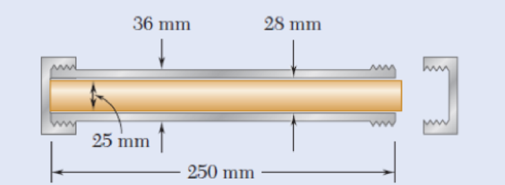
Fig. P2.16
a)
The average normal stress in the tube
Answer to Problem 16P
The average normal stress in the tube
Explanation of Solution
Given information:
The length of the tube (L) is
The outer diameter of the tube
The inner diameter of the tube
The Young’s modulus of the aluminium
The diameter of the rod
The Young’s modulus of the brass
The pitch of the single-threaded screw-on cover (p) is
The load act in the tube is P.
Calculation:
Calculate the cross sectional area of the tube
Substitute
Calculate the cross sectional area of the rod
Substitute
Calculate the deformation of the tube
Substitute
Calculate the deformation of the rod
Substitute
Calculate the deformation of the screw
Substitute
Calculate the load (P) act in the tube using the formula:
Substitute
Calculate the average normal stress in the tube
Substitute
Calculate the average normal stress in the rod
Substitute
Hence, the average normal stress in the tube
b)
The deformations of the tube
Answer to Problem 16P
The deformations of the tube
Explanation of Solution
Given information:
The length of the tube (L) is
The outer diameter of the tube
The inner diameter of the tube
The Young’s modulus of the aluminium
The diameter of the rod
The Young’s modulus of the brass
The pitch of the single-threaded screw-on cover (p) is
The load act in the tube is P.
Calculation:
Calculate the cross sectional area of the tube
Substitute
Calculate the cross sectional area of the rod
Substitute
Calculate the deformation of the tube
Substitute
Calculate the deformation of the rod
Substitute
Calculate the deformation of the screw
Substitute
Calculate the load (P) act in the tube using the formula:
Substitute
Calculate the deformations of the tube
Substitute
Calculate the deformations of the rod
Substitute
Hence, the deformations of the tube
Want to see more full solutions like this?
Chapter 2 Solutions
Mechanics of Materials, 7th Edition


- A 20 mm diameter rod BC has flat ends of 20 mm x 40 mm rectangular cross section, while the boom AB has a 30 x 50 mm rectangular cross section and is fitted with a clevis at the end B. Both members are connected at B by a pin from which the 30 kN load is suspended by means of a U-Shaped bracket. Boom AB is supported at A by a pin fitted into a double bracket, while rod BC is connected at C to a single bracket. All pins are 25 mm diameter. Determine the normal stresses in members AB and BC; shearing stresses and bearing stresses at A, B and C.arrow_forwardA solid square steel bar is fixed at one end as shown, and is loaded with a 25 kg weight. If the limiting stress of the bar is 27.24 kPa determine the cross sectional area of the steel square bar and its dimensions.arrow_forwardA solid aluminum [E = 64 GPa] rod (1) is connected to a solid bronze [E = 114 GPa] rod (2) at flange B, as shown. Aluminum rod (1) has an outside diameter of 36 mm and bronze rod (2) has an outside diameter of 17 mm. The normal stress in the aluminum rod must be limited to 124 MPa, and the normal stress in the bronze rod must be limited to 92 MPa. Assume L1 = 168 mm and L2 = 399 mm. Determine: (a) the maximum downward load P that may be applied at flange B. (Answer: P = 146kN)(b) the deflection vB (downward is positive) of flange B at the load determined in part(a). (Answer: vB = .322 mm)arrow_forward
- The rivet group connects two narrow lengths of plate, one of which carries a 15 kN load. If the ultimate shear strength t of a rivet is 350 N/mm² and its failure strength in compression stress is 600 N/mm², determine the minimum allowable values of rivet diameter d (mm) and plate thickness t (mm).arrow_forwardA solid 71-mm-diameter cold-rolled brass [G = 36.7 GPa] shaft that is 1.28 m long extends through and is completely bonded to a hollow aluminum [G = 25.9 GPa] tube. Aluminum tube (1) has an outside diameter of 95 mm, an inside diameter of 71 mm, and a length of 0.87 m. Both the brass shaft and the aluminum tube are securely attached to the wall support at A. Assume L1=L2 = 0.87 m, L3= 0.41 m, TB = 29 kN-m, and TC = 8 kN-m. When the two torques shown are applied to the composite shaft, determine:(a) the maximum shear stress magnitude T1 in aluminum tube(b) the maximum shear stress magnitude T2 and T3 in brass shaft segment(c) the rotation angle of joint B and joint Carrow_forwardA pulley is supported by a circular pin at A. The pin has a diameter of d = 0.375 in., and each side of the pulley support bracket has a thickness of t = 0.1875 in. The average shear stress in the pin cannot exceed 40 ksi, and the bearing stress in the pulley support bracket cannot exceed 65 ksi. Determine the maximum value of Pmax that can be supported by the assembly.arrow_forward
- Each of the four vertical Ilinks has an 8 x 36-mm uniform rectangular cross section and each of the four pins has a 16-mm diameter. Take P= 19 kN. 0.4 m C 0.25 m 0.2 m B. P Determine the average bearing stress at Bin member ABC, knowing that this member has a 10 x 50-mm uniform rectangular cross section. MPa. The average bearing stress at Bin member ABC is.arrow_forwardTwo cylindrical rods, one of steel and the other of brass, are joined at C and restrained by rigid supports at A and E. The steel rod has a length of 300 mm while the brass rod has a length of 200 mm. The diameters of the rods are shown in the figure below. A force of 60 kN is applied at point B of the steel segment. For the loading shown and knowing that modulus of elasticity values for steel and brass are respectively Es = 200 GPa and Eb = 105 GPa, determine a.) The reactions at A and E: RA and RE. b.) The deflection of point C from its original location. how to doarrow_forwardFrom the given bracket shown, which consist of two plates riveted to the column by 4-22mm Ø rivets which is subjected to an eccentric load of 150 kN. 1. Which of the following gives the shearing stress due to axial load only? a. 49.325 MPa b. 70.25 MPa c. 80.47 MPa d. 68.25 MPa 2.. Which of the following gives the shearing stress due to moment alone? a. 69.76 MPa b. 70.94 MPa c. 56.39 MPa d. 64.32 MPa 3. Which of the following gives the maximum shearing stress? a. 110.30 MPa b. 120.40 MPa c. 140.50 MPa d. 105.70 MPaarrow_forward
- A double riveted butt joint, in which the pitch of the rivets in the outer rows is twice that in the inner Rows, connects two 16mm thick plates with two cover plates each 12 mm thick. The diameter of rivets is 22 mm. Determine the pitches of the rivets in the two rows if the working stresses are not to exceed the following limits: Tensile stress in plates =100 MPa; Shear stress in rivets =75 MPa; and bearing stress in rivets and plates =150 MPa. Make a fully dimensioned sketch of the joint by showing at least two views.arrow_forward1. The structure is used to support a distributed load of w = 15 kN/m. The bolts at A, B, and C each have a diameter of 16 mm and each bolt is used in a double shear connection. The cross-sectional area of axial member (1) is 3,080 mm^2. The allowable stress in axial member (1) is 50 MPa and 280 MPa for the bolts. Determine the factor of safety with respect to the specified allowable stresses for axial member (1) and bolt at C.arrow_forwardThe brass tube AB (E = 105 GPa) has a cross-sectional areaof 138 mm² and is fitted with a plug at A. The tube is attached atB to a rigid plate that is itself attached at C to the bottom of analuminum cylinder (E = 70 GPa) with a cross-sectional areaof 250 mm². The cylinder is then hung from a support at D. In orderto close the cylinder, the plug must move down through 1.2 mm. Determine the force P that must be applied to the cylinder.arrow_forward
 Elements Of ElectromagneticsMechanical EngineeringISBN:9780190698614Author:Sadiku, Matthew N. O.Publisher:Oxford University Press
 Mechanics of Materials (10th Edition)Mechanical EngineeringISBN:9780134319650Author:Russell C. HibbelerPublisher:PEARSON
 Thermodynamics: An Engineering ApproachMechanical EngineeringISBN:9781259822674Author:Yunus A. Cengel Dr., Michael A. BolesPublisher:McGraw-Hill Education
 Control Systems EngineeringMechanical EngineeringISBN:9781118170519Author:Norman S. NisePublisher:WILEY
 Mechanics of Materials (MindTap Course List)Mechanical EngineeringISBN:9781337093347Author:Barry J. Goodno, James M. GerePublisher:Cengage Learning
 Engineering Mechanics: StaticsMechanical EngineeringISBN:9781118807330Author:James L. Meriam, L. G. Kraige, J. N. BoltonPublisher:WILEY