
Concept explainers
Videos
Two tempered-steel bars, each
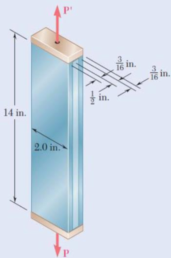
Fig. P2.111
Want to see the full answer?
Check out a sample textbook solution
Chapter 2 Solutions
Mechanics of Materials, 7th Edition


- Axial loads are applied with rigid bearing plates to the solid cylindrical rods shown. The normal stress in aluminum rod (1) must be limited to 20 ksi, the normal stress in brass rod (2) must be limited to 24 ksi, and the normal stress in steel rod (3) must be limited to 12 ksi. Determine the minimum diameter required for each of the three rods. Assume P = 8 kips, Q = 5 kips, R = 20 kips and S = 28 kips. Calculate F1, F2, F3 and..arrow_forwardAxial loads are applied with rigid bearing plates to the solid cylindrical rods shown. The normal stress in aluminum rod (1) must be limited to 19 ksi, the normal stress in brass rod (2) must be limited to 22 ksi, and the normal stress in steel rod (3) must be limited to 14 ksi. Determine the minimum diameter required for each of the three rods. Assume P = 9 kips, Q = 5 kips, R = 20 kips and S = 30 kips. (1) VQ B (2) (3) D First: Calculate the internal force (positive if tensile, negative if compresive) in rod (1). Use a FBD cutting through the rod in the section that includes the free end A. Answer: F1 = i kips.arrow_forwardAxial loads are applied with rigid bearing plates to the solid cylindrical rods shown. The normal stress in aluminum rod (1) must be limited to 19 ksi, the normal stress in brass rod (2) must be limited to 22 ksi, and the normal stress in steel rod (3) must be limited to 13 ksi. Determine the minimum diameter required for each of the three rods. Assume P = 7 kips, Q = 2 kips, R = 16 kips and S = 20 kips.arrow_forward
- Axial loads are applied with rigid bearing plates to the solid cylindrical rods shown. The normal stress in aluminum rod (1) must be limited to 19 ksi, the normal stress in brass rod (2) must be limited to 24 ksi, and the normal stress in steel rod (3) must be limited to 12 ksi. Determine the minimum diameter required for each of the three rods. Assume P = 9 kips, Q = 4 kips, R = 18 kips and S = 21 kips. Calculate the internal force (positive if tensile, negative if compresive) in rod (1). Use a FBD cutting through the rod in the section that includes the free end A.Answer: F1 = ? kips.arrow_forwardAxial loads are applied with rigid bearing plates to the solid cylindrical rods shown. The normal stress in aluminum rod (1) must be limited to 19 ksi, the normal stress in brass rod (2) must be limited to 24 ksi, and the normal stress in steel rod (3) must be limited to 12 ksi. Determine the minimum diameter required for each of the three rods. Assume P = 9 kips, Q = 4 kips, R = 18 kips and S = 21 kips.Calculate the internal force (positive if tensile, negative if compresive) in rod (1). Use a FBD cutting through the rod in the section that includes the free end A.arrow_forward1. A steel rod with a cross sectional area of 150 sq.mm is stretched between two fixed points. The tensile load at 20 deg C is 5000 N. At what temperature will the stress be zero. Assume a=11.7μm/m - degC and E=200GPaarrow_forward
- A bronzebar 3 m long with a cross sectional area of 320 mm 2 is placed between two rigid walls. At atemperature of 20 C, the gap is 25 mm. Find the temperature at which the compressive stress in the barwill be 35 MPa. Use α = 18.0 × 10 6 C and E = 80 GPaarrow_forwardA compressive load of 2.4 kN acts on a circular bar of 200 sq. mm area and 20 mm high. It experiences a compression of 0.15 mm. Then, the Young's Modulus of the material isarrow_forward40-mm Rod ABC consists of two cylindrical portions AB and BC; it is made of a mild steel that is assumed to be elastoplastic with E = 200 GPa and oy = 250 MPa. A force P is applied to the rod and then removed to give it a permanent set 8, = 2 mm. Determine the maximum value of the force P and the maximum amount 8, by which the rod should be stretched to give it the desired permanent 1.2 m diameter B 30-mm 0,8 m diameter set. Parrow_forward
- A 12mm thick steel tire has a width of 110mm and has an internal diameter of 800mm. The tire is heated and shrunk to a steel wheel 800.5 mm in diameter. The modulus of elasticity E = 200 MPa. a. Determine the tensile stress in the tire. b. Determine the compressive pressure between the tire and the wheel. c. Determine the thickness of the tire to resist a pressure of 1.5 MPa if it has an allowable stress of 124 MPa. I need answer ASAP. Thank you!arrow_forwardRigid bar ABC is supported by bronze rod (1) and aluminum rod (2), as shown. A concentrated load P is applied to the free end of aluminum rod (3). Bronze rod (1) has an elastic modulus of E₁ = 15,000 ksi and a diameter of d₁ = 0.45 in. Aluminum rod (2) has an elastic modulus of E₂ = 10,000 ksi and a diameter of d₂ = 0.70in. Aluminum rod (3) has a diameter of d3= 0.95in. The yield strength of the bronze is 48 ksi and the yield strength of the aluminum is 40 ksi. Assume a = 2.5 ft, b = 1.5 ft, L₁= 6 ft, L₂= 8 ft, and L3= 3 ft. (a) Determine the magnitude of load P that can safely be applied to the structure if a minimum factor of safety of 2.0 is required. (b) Determine the deflection of point D for the load determined in part (a). (c) The pin used at B has an ultimate shear strength of 55 ksi. If a factor of safety of 2.5 is required for this double shear pin connection, determine the minimum pin diameter that can be used at B. 5 L₁ A₁ = A₂ = A A3 = i Bronze (1) i a B Aluminum (3)…arrow_forwardTwo vertical wires are suspended at 450 mm apart. Their lower ends support a rigid horizontal bar that carries a load F. The left-hand wire is made of copper and has a diameter of 3 mm. The right-hand wire is made of steel and has a diameter of 2 mm. Calculate: (a) The position of F if the elongation in both wires is the same. (b) The load carried by each wire and the total elongation if F = 350 N and both wires are initially 3,5 m long. (Esteel = 200 GPa and Ecopper = 100 GPa).arrow_forward
 Elements Of ElectromagneticsMechanical EngineeringISBN:9780190698614Author:Sadiku, Matthew N. O.Publisher:Oxford University Press
 Mechanics of Materials (10th Edition)Mechanical EngineeringISBN:9780134319650Author:Russell C. HibbelerPublisher:PEARSON
 Thermodynamics: An Engineering ApproachMechanical EngineeringISBN:9781259822674Author:Yunus A. Cengel Dr., Michael A. BolesPublisher:McGraw-Hill Education
 Control Systems EngineeringMechanical EngineeringISBN:9781118170519Author:Norman S. NisePublisher:WILEY
 Mechanics of Materials (MindTap Course List)Mechanical EngineeringISBN:9781337093347Author:Barry J. Goodno, James M. GerePublisher:Cengage Learning
 Engineering Mechanics: StaticsMechanical EngineeringISBN:9781118807330Author:James L. Meriam, L. G. Kraige, J. N. BoltonPublisher:WILEY