
Concept explainers
Videos
Determine the maximum load P that can be applied to the brass bar of Prob. 2.55 if the allowable stress in the steel bars is 30 MPa and the allowable stress in the brass bar is 25 MPa.
2.55 Two steel bars (Es = 200 GPa and αs = 11.7 × 10⁻⁶/°C) are used to reinforce a brass bar (Eb = 105 GPa, αb = 20.9 × 10⁻⁶/°C) that is subjected to a load P = 25 kN. When the steel bars were fabricated, the distance between the centers of the holes that were to fit on the pins was made 0.5 mm smaller than the 2 m needed. The steel bars were then placed in an oven to increase their length so that they would just fit on the pins. Following fabrication, the temperature in the steel bars dropped back to room temperature. Determine (a) the increase in temperature that was required to fit the steel bars on the pins, (b) the stress in the brass bar after the load is applied to it.
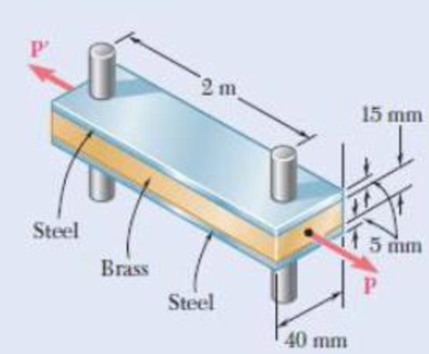
Fig. P2.55
Want to see the full answer?
Check out a sample textbook solution
Chapter 2 Solutions
Mechanics of Materials, 7th Edition


- Drawing the section view for the following multiview drawing AutoCAD you see the section pratice I need to show how to autocadarrow_forwardA boiler with 80% efficiency produces steam at 40bar and 500 C at a rate of 1.128kg/s. The temperature of the feed water is raised from 25 C to 125 C in the economizer and the ambient air is drawn to the boiler at a rate of 2.70 kg/s at 16 C. The flue gases leave the chimney at rate of 3 kg/s at 150 C with specific heat of 1.01 kJ/kg.K. The dryness fraction of steam collected in the steam drum is 0.95. 1- Determine the heat value of the fuel. 2- The equivalence evaporation. 3- Draw the heat balance sheet.arrow_forwardA rotating shaft is made of 42 mm by 4 mm thick cold-drawn round steel tubing and has a 6 mm diameter hole drilled transversely through it. The shaft is subjected to a pulsating torque fluctuating from 20 to 160 Nm and a completely reversed bending moment of 200 Nm. The steel tubing has a minimum strength of Sut = 410 MPa (60 ksi). The static stress-concentration factor for the hole is 2.4 for bending and 1.9 for torsion. The maximum operating temperature is 400˚C and a reliability of 99.9% is to be assumed. Find the factor of safety for infinite life using the modified Goodman failure criterion.arrow_forward
- I need help with a MATLAB code. This code just keeps running and does not give me any plots. I even reduced the tolerance from 1e-9 to 1e-6. Can you help me fix this? Please make sure your solution runs. % Initial Conditions rev = 0:0.001:2; g1 = deg2rad(1); g2 = deg2rad(3); g3 = deg2rad(6); g4 = deg2rad(30); g0 = deg2rad(0); Z0 = 0; w0 = [0; Z0*cos(g0); -Z0*sin(g0)]; Z1 = 5; w1 = [0; Z1*cos(g1); -Z1*sin(g1)]; Z2 = 11; w2 = [0; Z2*cos(g2); -Z2*sin(g2)]; [v3, psi3, eta3] = Nut_angle(Z2, g2, w2); plot(v3, psi3) function dwedt = K_DDE(~, w_en) % Extracting the initial condtions to a variable % Extracting the initial condtions to a variable w = w_en(1:3); e = w_en(4:7); Z = w_en(8); I = 0.060214; J = 0.015707; x = (J/I) - 1; y = Z - 1; s = Z; % Kinematic Differential Equations dedt = zeros(4,1); dedt(1) = pi*(e(3)*(s-w(2)-1) + e(2)*w(3) + e(4)*w(1)); dedt(2) = pi*(e(4)*(w(2)-1-s) + e(3)*w(1) - e(1)*w(3)); dedt(3) = pi*(-e(1)*(s-w(2)-1) - e(2)*w(1) + e(4)*w(3));…arrow_forwardalpha 1 is not zero alpha 1 can equal alpha 2 use velocity triangle to solve for alpha 1 USE MATLAB ONLY provide typed code solve for velocity triangle and dont provide copied answer Turbomachienery . GIven: vx = 185 m/s, flow angle = 60 degrees, (leaving a stator in axial flow) R = 0.5, U = 150 m/s, b2 = -a3, a2 = -b3 Find: velocity triangle , a. magnitude of abs vel leaving rotor (m/s) b. flow absolute angles (a1, a2, a3) 3. flow rel angles (b2, b3) d. specific work done e. use code to draw vel. diagram Use this code for plot % plots Velocity Tri. in Ch4 function plotveltri(al1,al2,al3,b2,b3) S1L = [0 1]; V1x = [0 0]; V1s = [0 1*tand(al3)]; S2L = [2 3]; V2x = [0 0]; V2s = [0 1*tand(al2)]; W2s = [0 1*tand(b2)]; U2x = [3 3]; U2y = [1*tand(b2) 1*tand(al2)]; S3L = [4 5]; V3x = [0 0]; V3r = [0 1*tand(al3)]; W3r = [0 1*tand(b3)]; U3x = [5 5]; U3y = [1*tand(b3) 1*tand(al3)]; plot(S1L,V1x,'k',S1L,V1s,'r',... S2L,V2x,'k',S2L,V2s,'r',S2L,W2s,'b',U2x,U2y,'g',...…arrow_forward3. Find a basis of eigenvectors and diagonalize. 4 0 -19 7 a. b. 1-42 16 12-20 [21-61arrow_forward
- 2. Find the eigenvalues. Find the corresponding eigenvectors. 6 2 -21 [0 -3 1 3 31 a. 2 5 0 b. 3 0 -6 C. 1 1 0 -2 0 7 L6 6 0 1 1 2. (Hint: λ = = 3)arrow_forwardUSE MATLAB ONLY provide typed code solve for velocity triangle and dont provide copied answer Turbomachienery . GIven: vx = 185 m/s, flow angle = 60 degrees, (leaving a stator in axial flow) R = 0.5, U = 150 m/s, b2 = -a3, a2 = -b3 Find: velocity triangle , a. magnitude of abs vel leaving rotor (m/s) b. flow absolute angles (a1, a2, a3) 3. flow rel angles (b2, b3) d. specific work done e. use code to draw vel. diagram Use this code for plot % plots Velocity Tri. in Ch4 function plotveltri(al1,al2,al3,b2,b3) S1L = [0 1]; V1x = [0 0]; V1s = [0 1*tand(al3)]; S2L = [2 3]; V2x = [0 0]; V2s = [0 1*tand(al2)]; W2s = [0 1*tand(b2)]; U2x = [3 3]; U2y = [1*tand(b2) 1*tand(al2)]; S3L = [4 5]; V3x = [0 0]; V3r = [0 1*tand(al3)]; W3r = [0 1*tand(b3)]; U3x = [5 5]; U3y = [1*tand(b3) 1*tand(al3)]; plot(S1L,V1x,'k',S1L,V1s,'r',... S2L,V2x,'k',S2L,V2s,'r',S2L,W2s,'b',U2x,U2y,'g',... S3L,V3x,'k',S3L,V3r,'r',S3L,W3r,'b',U3x,U3y,'g',...... 'LineWidth',2,'MarkerSize',10),...…arrow_forwardUSE MATLAB ONLY provide typed code solve for velocity triangle and dont provide copied answer Turbomachienery . GIven: vx = 185 m/s, flow angle = 60 degrees, R = 0.5, U = 150 m/s, b2 = -a3, a2 = -b3 Find: velocity triangle , a. magnitude of abs vel leaving rotor (m/s) b. flow absolute angles (a1, a2, a3) 3. flow rel angles (b2, b3) d. specific work done e. use code to draw vel. diagram Use this code for plot % plots Velocity Tri. in Ch4 function plotveltri(al1,al2,al3,b2,b3) S1L = [0 1]; V1x = [0 0]; V1s = [0 1*tand(al3)]; S2L = [2 3]; V2x = [0 0]; V2s = [0 1*tand(al2)]; W2s = [0 1*tand(b2)]; U2x = [3 3]; U2y = [1*tand(b2) 1*tand(al2)]; S3L = [4 5]; V3x = [0 0]; V3r = [0 1*tand(al3)]; W3r = [0 1*tand(b3)]; U3x = [5 5]; U3y = [1*tand(b3) 1*tand(al3)]; plot(S1L,V1x,'k',S1L,V1s,'r',... S2L,V2x,'k',S2L,V2s,'r',S2L,W2s,'b',U2x,U2y,'g',... S3L,V3x,'k',S3L,V3r,'r',S3L,W3r,'b',U3x,U3y,'g',...... 'LineWidth',2,'MarkerSize',10),... axis([-1 6 -4 4]), ...…arrow_forward
- The answer should equal to 1157. Please sent me the solution. Thank you!arrow_forwardBONUS: If the volume of the 8cm x 6.5cm x 6cm Block of Aluminum was 312cm3 before machining, find how much material was removed when the fixture below was machined. +2 2.00 cm 6.00 cm 2.50 cm 6.50 cm 1.00 cm 2.50 cm 11.00 cm 8.00 cm 30 CP 9411 FL.4) (m² 1157 Area of triangle = 1/2*B*H Area of circle = лR² Circumference of a circle = 2πR 6.00 cm 6.50 cm 1.50 cm Radius 1.50 cm 1.00 cmarrow_forwardConsider a 5m by 5m wet concret patio with an average water film thickness of .2mm. Now wind at 50 km/h is blowing over the surface. If the air is at 1 atm, 15oC and 35 percent relative humidity, determine how long it will take for the patio to completely dry.arrow_forward
 Mechanics of Materials (MindTap Course List)Mechanical EngineeringISBN:9781337093347Author:Barry J. Goodno, James M. GerePublisher:Cengage Learning