
Videos
In many situations it is known that the normal stress in a given direction is zero. For example, ϭz = 0 in the case of the thin plate shown. For this case, which is known as plane stress, show that If the strains ∈x and ∈y have been determined experimentally, we can express ϭx, ϭy and ∈z as follows:
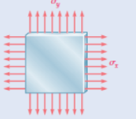
Fig. P2.73
Want to see the full answer?
Check out a sample textbook solution
Chapter 2 Solutions
Mechanics of Materials, 7th Edition


- A thin wire, lying along the x axis, is strained such that each point on the wire is displaced Δx = kx2 along the x axis. If k is constant, what is the normal strain at any point P along the wire?arrow_forwardIn many situations it is known that the normal stress in a given direc-tion is zero. For example, σz= 0 in the case of the thin plate shown. For this case, which is known as plane stress, show that if the strains εx and εy have been determined experimentally, we can express σx, σyand εz as follows:arrow_forwardA 45° strain rosette was placed on the surface of a critical point on an engineering part. The following were measured: Ea = 400 μ C ли 45° mm mm 45° ли Gauge a was aligned with the x-axis. a. Determine Ex, Ey, Yxy b. Using Mohr's Circle, find the principal strains and the maximum shear strain at that point, and find the orientation of the principal planes from the given x-y axes. y ли & = 450 μ ஆ b a mm X mm & c = 500 μ y+ ос mm mm eb 10₂ Xarrow_forward
- The material is subjected to biaxial loading producing uniform normal stress x and y as shown. The strains are Strainx=−0.00065 and Strainy=−0.00040. Use E=30×106 psi and v=0.30. Determine the following: (a) stress at x. Indicate tension or compression. Use 2 decimal places. (b) stress at y. Indicate tension or compression. Use 2 decimal places. (c) Change in the thickness of the material. Indicate elongation or contraction. Use 5 decimal places and scientific notation of ×10−3(Example: _ . _ _ _ _ _ ×10−3)arrow_forwardThe force applied at the handle of the rigid lever causes the lever to rotate clockwise about the pin B through an angle of 1.6°. The wires are unstretched when the lever is in the horizontal position. (Figure 1) Figure A 200 mm G ,200 mm 300 mm- -H C FY 200 mm 300 mm D E 1 of 1 Part A Determine the average normal strain developed in wire AH. Express your answer using three significant figures. ΠΑΣΦ Τ (EAH) avg= Submit Part B (ECC) avg= Determine the average normal strain developed in wire CG. Express your answer using three significant figures. Submit Part C Request Answer (EDP) avg= vec • VAΣo↓ vec ΠΙΑΣΦΑ Request Answer 4 Determine the average normal strain developed in wire DF. Express your answer using three significant figures. ΠΑΣΦΑ vec ↑ ? ? ? mm/mm mm/mm mm/mmarrow_forward. The normal stresses at a point in a steel member are δx = 8 ksi, δy = -4 ksi and δz = 10 ksi. Using E = 29 x 103 ksi and v = 0.3, determine the normal strains at this point.arrow_forward
- 1- Consider a 50 mm × 50 mm × 50 mm element of graphite-reinforced material with its fibersoriented at 45◦ and constrained against deformation in the x direction. The element isheated 50◦C. What is the stress σx required to enforce this constraint and what are the strainsεy, γxy, and εz?2- Consider a 45° off-axis tensile test coupon. Three strain gages attached as shown beloware reading ε1 = 0.00647, ε2 = −0.00324, and ε3 = 0.008095 at stress level of σx =100 MPa.Determine the off-axis modulus of elasticity Ex the off-axis major Poisson’s ratio ??? andcoefficient of mutual influence of the second kind ???,?.arrow_forward(b) Three strain gauges were arranged in the form of a rectangular rosette and positioned on a test surface, the measured strains were as follows: 81-350 x 10 82-110x 10 E=230 x 10 Determine (1) the principle strains; (1) the principle stresses, the direction of the greater principle strain relative to gauge I. Also draw the Mohr's Strain Cirele. Take the Modulus of Elasticity value to be E-210 GN/m and Poisson's ratio - 0.3.arrow_forwardA 60 ̊ strain rosette measures the following strain at a point on the aluminum skin of an airplane. ε0 = 160 ×10-6 m/m, ε60 = -220 ×10-6 m/m and ε120 = 360 ×10-6 m/m. Using E= 10 ×106 psi and v = 0.3, Determine the principle stresses and the maximum in-plane shear stress.arrow_forward
- A thin polymer plate PQR is deformed such that corner Q is displaced downward a distance L = 0.10 in. to new position Q' as shown. Determine the magnitude of the shear strain at Q' associated with the two edges (PQ and QR). P 25 in. 7982 μrad 6862 μrad 09533 μrad O6186 prad O8600 μrad 4 in. R 10 in. L Xarrow_forwardThe state of plane strain on an element is represented by the following components: Ex =D340 x 10-6, ɛ, = , yxy Ey =D110 x 10-6, 3D180 x10-6 ху Draw Mohr's circle to represent this state of strain. Use Mohrs circle to obtain the principal strains and principal plane.arrow_forwardA single strain gage forming an angle = 18° with a horizontal plane is used to determine the gage pressure in the cylindrical steel tank shown. The cylindrical wall of the tank is 6 mm thick, has a 600-mm inside diameter, and is made of a steel with E= 200 GPa and v = 0.30. Determine the pressure in the tank indicated by a strain gage reading of 320μ. (Round the final answer to three decimal places.) The pressure in the tank is MPa.arrow_forward
 Elements Of ElectromagneticsMechanical EngineeringISBN:9780190698614Author:Sadiku, Matthew N. O.Publisher:Oxford University Press
 Mechanics of Materials (10th Edition)Mechanical EngineeringISBN:9780134319650Author:Russell C. HibbelerPublisher:PEARSON
 Thermodynamics: An Engineering ApproachMechanical EngineeringISBN:9781259822674Author:Yunus A. Cengel Dr., Michael A. BolesPublisher:McGraw-Hill Education
 Control Systems EngineeringMechanical EngineeringISBN:9781118170519Author:Norman S. NisePublisher:WILEY
 Mechanics of Materials (MindTap Course List)Mechanical EngineeringISBN:9781337093347Author:Barry J. Goodno, James M. GerePublisher:Cengage Learning
 Engineering Mechanics: StaticsMechanical EngineeringISBN:9781118807330Author:James L. Meriam, L. G. Kraige, J. N. BoltonPublisher:WILEY