
Introductory Circuit Analysis (13th Edition)
13th Edition
ISBN: 9780133923605
Author: Robert L. Boylestad
Publisher: PEARSON
expand_more
expand_more
format_list_bulleted
Concept explainers
Videos
Textbook Question
Chapter 10, Problem 45P
For the circuit in Fig. 10.113:
a. Find the mathematical expressions for the transient behavior of the voltage UC and the current iC following the closing of the switch.
b. Sketch the waveforms of UC and iC.
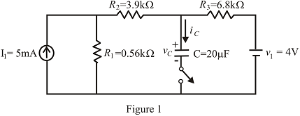
Fig. 10.113
Expert Solution & Answer
Want to see the full answer?
Check out a sample textbook solution
Students have asked these similar questions
Q1)Design moving coil ammeter as a voltmeter to read 15 V (RMS)
alternating voltage. If the internal resistance of the ammeter is 5 KQ , the
voltage across the internal resistance is 0.5 v and the resistance of the
diodes in the forward direction is 1 KQ, find the multiplier resistance and
sensitivity . Assume half wave rectification and a shunt resistance across
the meter. The value of the shunt resistance across the ammeter is 2.5 KQ.
Q2) Re-design the question above for full wave rectifier (without Rsh)
In the figure given we have u(t)=10. cosot [V]. We assume the diodes
and the A-meter (A) to be ideal.
A
u(t)
a) Plot the waveform of the current flowing through the A-m in scale.
b) What is the reading of the A-m, if it is moving-coil type?
c) What is the reading of the A-m, if it is moving-iron type?
d) Calculate the power factor of the WHOLE structure.
R1 1
R2
102
Full-wave rectified sine wave circuit is used to measure the RMS value of a half square wave with the help of PMMC meter. The meter was actually calibrated for sine wave. The circuit uses a meter movement with a full scale deflection current of 200uA and internal meter resistance of 5kΩ. Assuming Non-ideal diodes having resistance 1kΩ, Analyze the circuit to determine the value of series multiplier resister and the corrected RMS voltage, if meter is to read 225V RMS full-scale.
Chapter 10 Solutions
Introductory Circuit Analysis (13th Edition)
Ch. 10 - a. Find the electric field strength at a point 1 m...Ch. 10 - The electric field strength is 72 newtons/coulomb...Ch. 10 - Find the capacitance of a parallel plate capacitor...Ch. 10 - How much charge is deposited on the plates of a...Ch. 10 - a. Find the electric field strength between the...Ch. 10 - A 6.8 pF parallel plate capacitor has 160 C of...Ch. 10 - Find the capacitance of a parallel plate capacitor...Ch. 10 - Repeat Problem 7 if the dielectric is...Ch. 10 - Find the distance in mils between the plates of a...Ch. 10 - The capacitance of a capacitor with a dielectric...
Ch. 10 - The plates of a parallel plate capacitor with a...Ch. 10 - A parallel plate air capacitor has a capacitance...Ch. 10 - Find the maximum voltage that can be applied...Ch. 10 - Find the distance in micrometers between the...Ch. 10 - A 22 pF capacitor has -200 ppm/C at room...Ch. 10 - What is the capacitance of a small teardrop...Ch. 10 - A large, flat, mica capacitor is labeled 471F....Ch. 10 - A small, flat, disc ceramic capacitor is labeled...Ch. 10 - For the circuit in Fig. 10.94, composed of...Ch. 10 - Repeat Problem 19 for R=100k, and compare the...Ch. 10 - For the circuit in Fig. 10.95, composed of...Ch. 10 - For the circuit in Fig. 10.96, composed of...Ch. 10 - Prob. 23PCh. 10 - The voltage across a 10 F capacitor in a series...Ch. 10 - For the R-C circuit in Fig. 10.97. composed of...Ch. 10 - For the network in Fig. 10.98. composed of...Ch. 10 - For the network in Fig.10.99.composed of standard...Ch. 10 - The 1000 F capacitor in Fig.10.100 is charged to...Ch. 10 - The capacitor in Fig. 10.101 is initially charged...Ch. 10 - Repeat Problem 29 if the initial charge is -40V.Ch. 10 - Repeat Problem 29 if the initial charge is +40V.Ch. 10 - The capacitor in Fig. 10.102 is initially charged...Ch. 10 - The capacitor in Fig. 10.103 is initially charged...Ch. 10 - The capacitor in Fig. 10.104 is initially charged...Ch. 10 - The capacitors of Fig. 10.105 are initially...Ch. 10 - Repeat Problem 35 if a 10 k resistor is placed in...Ch. 10 - Given the expression vc=140mV(1-e-t/2ms) a....Ch. 10 - For the automobile circuit of Fig. 10.106. VL must...Ch. 10 - Design the network in Fig.10.107 such that the...Ch. 10 - For the circuit in Fig. 10.108: a. Find the time...Ch. 10 - For the system in Fig. 10.109. using a DMM with a...Ch. 10 - For the circuit in Fig. 10.110: a. Find the...Ch. 10 - The capacitor in Fig. 10.111 is initially charged...Ch. 10 - The capacitors in Fig. 10.112 are initially...Ch. 10 - For the circuit in Fig. 10.113: a. Find the...Ch. 10 - The capacitor in Fig. 10.114 is initially charged...Ch. 10 - For the system in Fig. 10.115, using a DMM with a...Ch. 10 - Find the waveform for the average current if the...Ch. 10 - Find the waveform for the average current if the...Ch. 10 - Given the waveform in Fig.10.118 for the current...Ch. 10 - Find the total capacitance CT for the network in...Ch. 10 - Find the total capacitance CT for the network in...Ch. 10 - Find the steady-state voltage across and the...Ch. 10 - Find the steady-state voltage across and the...Ch. 10 - For the configuration in Fig. 10.123, determine...Ch. 10 - For the configuration in Fig.10.124, determine the...Ch. 10 - Find the energy stored by a 120 pF capacitor with...Ch. 10 - If the energy stored by a 6 F capacitor is 1200 J,...Ch. 10 - For the network in Fig. 10.125, determine the...Ch. 10 - An electronic flashgun has a 1000 F capacitor that...Ch. 10 - Using PSpice or Multisim, verify the results in...Ch. 10 - Using the initial condition operator, verify the...Ch. 10 - Using PSpice or Multisim, verify the results for...Ch. 10 - Using PSpice or Multisim, verify the results in...
Knowledge Booster


Learn more about
Need a deep-dive on the concept behind this application? Look no further. Learn more about this topic, electrical-engineering and related others by exploring similar questions and additional content below.Similar questions
- In the figure given we have u(t)=10- cosot [V]. We assume the diodes and the A-meter (A) to be ideal. a) Plot the waveform of the current flowing through the A-m in scale. A u(t) b) What is the reading of the A-m, if it is moving-coil type? R1 R2 c) What is the reading of the A-m, if it is moving-iron type? 50 102 d) Calculate the power factor of the WHOLE structure.arrow_forwardA DA Vm sin cor For the following single-phase full-wave diode rectifier, Vm = 311 V, R = 1 N, L = 0.002 H and the source frequency is given as 50 Hz. Welding current Find the THD. Note: You can consider calculating the effective value of the welding current and the effective value of the fundamental wave of the welding current. wwarrow_forward5. A voltage source produces a "Triangle" wave and is connected to a series diode and resistor circuit as shown. D1 KH D V1 #1 V R1 R Using the nominal piecewise linear model for a diode, determine from the following possibilities the graph that best represents the voltage across the resistor? (Delete those that do not apply) (Blue curve VR, dashed curve V1). Then determine which graph best represents the voltage across the diode.arrow_forward
- A- If V, is a sinusoidal voltage with Vm = 40 V, and V= 15 V. Plot the waveform of the output voltage in each of the following clippers circuits assuming ideal diodes. B- Repeat part (A) if the diodes are silicon diodes. R R R (a) (b) (c) (d)arrow_forward9. The following circuit is a voltage limiting circuit. The diode has an offset voltage of 0.7 V. (a) Determine the maximum & minimum voltages for Vout(t) for both the positive and negative cycles of Vin(t) (b) Calculate the maximum current flow during the positive cycle of Vin(t) (c) Sketch the waveforms for Vin(t) and Vout(t) for 2 cycles, indicate on the waveform the period, maximum and minimum values. (d) Sketch the output waveform Vout(t) if Vin(t) is set to 10 V pp. Vin(t) Vp = 12 V 50 Hz 470 Ω 5 V Vout(t)arrow_forwardAssuming that the Zener diode turns on, how much is the current that circulates through the load resistance. Select one: A. 10 mA B. 15 mA. C. 19 mA. D. 34 mA.arrow_forward
- Three Phase Uncontrolled Half Wave Rectifiers find the value of Voltage and Currents (output de and Root Mean Square) with all the proved, then sketch the curve from 0-2 on these axes (vs, vo, ia, ib, ic, io) explain its operation.arrow_forward7. For a certain 12 V zener diode, a 10 mA change in zener current produces a 0.1 V change in zener voltage. The zener impedance for this current range is a. 12 b. 100 Q c. 10 Qarrow_forwardAN Sesli oku 1-In the circuit designed to measure the effective value of the sinusoidal voltage at the input, diodes are considered ideal. M deflection is a measuring element with rotating coil. Rm32k İm-(10)^-4 A. A- Draw the waveform of the current flowing through M on a scale. Determine the resistance value of R1 so that the nominal voltage value of V-m is 100V. B-What should the tolerances of the resistors be so that the Vm class is at most 1.5? (resistors have the same tolerances) ult) R2 本 R3 20k 18k R4 k: k2 10karrow_forward
- / Consider the circuit shown below with a transformer of 10:1 transformation ratio and the diodes are silicon. The input voltage is 120V RMS i. What is the name of the circuit? ii. What is the peak secondary voltage? iii. Find the voltage value across the resistor iv. What is the PIV for each diode? 120 VAC RL 10:1 ணைarrow_forwardQ: - Consider the circuit in Figure a) What type of circuit is this? b) Find and Sketch the voltage waveform across RL, assume the diodes are practical. 4:1 D, 120 V rms c) If sin wave with 100µf connected in parallel with the resistor, calculate the ripple сарacitor is 60 HZ 1.0 kN D2 factor lllee lelllarrow_forward(c) A 50 Hz sinusoidal AC voltage source of peak value V, = 340 V delivers power to a resistive load of 50 n. (1) Calculate the average power delivered. (i) The AC source is now connected to the load via a full wave diode bridge. The turn-on voltage of the diodes is 0.3 V. Calculate the peak voltage across the load and the average voltage across the load. (ii) Explain how a smoothing capacitor can be used to hold up the voltage across the load. Compare the efficiency of the rectifier with and without the smoothing capacitor. (iv) Define "regulation" as applied to the output voltage of a rectifier and explain why an LR filtered rectifier bridge provides better regulation of the load voltage than an RC filtered rectifier bridge.arrow_forward
arrow_back_ios
SEE MORE QUESTIONS
arrow_forward_ios
Recommended textbooks for you
 Introductory Circuit Analysis (13th Edition)Electrical EngineeringISBN:9780133923605Author:Robert L. BoylestadPublisher:PEARSON
 Delmar's Standard Textbook Of ElectricityElectrical EngineeringISBN:9781337900348Author:Stephen L. HermanPublisher:Cengage Learning
 Programmable Logic ControllersElectrical EngineeringISBN:9780073373843Author:Frank D. PetruzellaPublisher:McGraw-Hill Education
 Fundamentals of Electric CircuitsElectrical EngineeringISBN:9780078028229Author:Charles K Alexander, Matthew SadikuPublisher:McGraw-Hill Education
 Electric Circuits. (11th Edition)Electrical EngineeringISBN:9780134746968Author:James W. Nilsson, Susan RiedelPublisher:PEARSON
 Engineering ElectromagneticsElectrical EngineeringISBN:9780078028151Author:Hayt, William H. (william Hart), Jr, BUCK, John A.Publisher:Mcgraw-hill Education,
Introductory Circuit Analysis (13th Edition)
Electrical Engineering
ISBN:9780133923605
Author:Robert L. Boylestad
Publisher:PEARSON
Delmar's Standard Textbook Of Electricity
Electrical Engineering
ISBN:9781337900348
Author:Stephen L. Herman
Publisher:Cengage Learning
Programmable Logic Controllers
Electrical Engineering
ISBN:9780073373843
Author:Frank D. Petruzella
Publisher:McGraw-Hill Education
Fundamentals of Electric Circuits
Electrical Engineering
ISBN:9780078028229
Author:Charles K Alexander, Matthew Sadiku
Publisher:McGraw-Hill Education
Electric Circuits. (11th Edition)
Electrical Engineering
ISBN:9780134746968
Author:James W. Nilsson, Susan Riedel
Publisher:PEARSON
Engineering Electromagnetics
Electrical Engineering
ISBN:9780078028151
Author:Hayt, William H. (william Hart), Jr, BUCK, John A.
Publisher:Mcgraw-hill Education,
What is an electric furnace and how does it work?; Author: Fire & Ice Heating and Air Conditioning Inc;https://www.youtube.com/watch?v=wjAWecPGi0M;License: Standard Youtube License