
Introductory Circuit Analysis (13th Edition)
13th Edition
ISBN: 9780133923605
Author: Robert L. Boylestad
Publisher: PEARSON
expand_more
expand_more
format_list_bulleted
Concept explainers
Videos
Textbook Question
Chapter 10, Problem 22P
For the circuit in Fig. 10.96, composed of standard values:
a. Determine the time constant of the circuit.
b. Write the mathematical equation for the voltage Uc following the closing of the switch.
c. Write the mathematical expression for the current ic following the dosing of the switch.
d. Sketch the waveforms of Uc and ic.
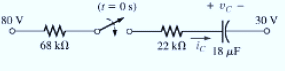
Fig. 10.96
Expert Solution & Answer
Want to see the full answer?
Check out a sample textbook solution
Students have asked these similar questions
Q1)Design moving coil ammeter as a voltmeter to read 15 V (RMS)
alternating voltage. If the internal resistance of the ammeter is 5 KQ , the
voltage across the internal resistance is 0.5 v and the resistance of the
diodes in the forward direction is 1 KQ, find the multiplier resistance and
sensitivity . Assume half wave rectification and a shunt resistance across
the meter. The value of the shunt resistance across the ammeter is 2.5 KQ.
Q2) Re-design the question above for full wave rectifier (without Rsh)
Q: - Consider the circuit in Figure
a) What type of circuit is this?
b) Find and Sketch the voltage
waveform across RL, assume
the diodes are practical.
4:1
D,
120 V rms
c) If
sin wave with
100µf
connected in parallel with the
resistor, calculate the ripple
сарacitor
is
60 HZ
1.0 kN
D2
factor
lllee
lelll
Q1)Design moving coil ammeter as a voltmeter to read 15 V (RMS)
alternating voltage. If the internal resistance of the ammeter is 5 K2, the
voltage across the internal resistance is 0.5 v and the resistance of the
diodes in the forward direction is 1 K2, find the multiplier resistance and
sensitivity. Assume half wave rectification and a shunt resistance across
the meter. The value of the shunt resistance across the ammeter is 2.5 KQ.
Q2) Re-design the question above for full wave rectifier (without Rsh)
Chapter 10 Solutions
Introductory Circuit Analysis (13th Edition)
Ch. 10 - a. Find the electric field strength at a point 1 m...Ch. 10 - The electric field strength is 72 newtons/coulomb...Ch. 10 - Find the capacitance of a parallel plate capacitor...Ch. 10 - How much charge is deposited on the plates of a...Ch. 10 - a. Find the electric field strength between the...Ch. 10 - A 6.8 pF parallel plate capacitor has 160 C of...Ch. 10 - Find the capacitance of a parallel plate capacitor...Ch. 10 - Repeat Problem 7 if the dielectric is...Ch. 10 - Find the distance in mils between the plates of a...Ch. 10 - The capacitance of a capacitor with a dielectric...
Ch. 10 - The plates of a parallel plate capacitor with a...Ch. 10 - A parallel plate air capacitor has a capacitance...Ch. 10 - Find the maximum voltage that can be applied...Ch. 10 - Find the distance in micrometers between the...Ch. 10 - A 22 pF capacitor has -200 ppm/C at room...Ch. 10 - What is the capacitance of a small teardrop...Ch. 10 - A large, flat, mica capacitor is labeled 471F....Ch. 10 - A small, flat, disc ceramic capacitor is labeled...Ch. 10 - For the circuit in Fig. 10.94, composed of...Ch. 10 - Repeat Problem 19 for R=100k, and compare the...Ch. 10 - For the circuit in Fig. 10.95, composed of...Ch. 10 - For the circuit in Fig. 10.96, composed of...Ch. 10 - Prob. 23PCh. 10 - The voltage across a 10 F capacitor in a series...Ch. 10 - For the R-C circuit in Fig. 10.97. composed of...Ch. 10 - For the network in Fig. 10.98. composed of...Ch. 10 - For the network in Fig.10.99.composed of standard...Ch. 10 - The 1000 F capacitor in Fig.10.100 is charged to...Ch. 10 - The capacitor in Fig. 10.101 is initially charged...Ch. 10 - Repeat Problem 29 if the initial charge is -40V.Ch. 10 - Repeat Problem 29 if the initial charge is +40V.Ch. 10 - The capacitor in Fig. 10.102 is initially charged...Ch. 10 - The capacitor in Fig. 10.103 is initially charged...Ch. 10 - The capacitor in Fig. 10.104 is initially charged...Ch. 10 - The capacitors of Fig. 10.105 are initially...Ch. 10 - Repeat Problem 35 if a 10 k resistor is placed in...Ch. 10 - Given the expression vc=140mV(1-e-t/2ms) a....Ch. 10 - For the automobile circuit of Fig. 10.106. VL must...Ch. 10 - Design the network in Fig.10.107 such that the...Ch. 10 - For the circuit in Fig. 10.108: a. Find the time...Ch. 10 - For the system in Fig. 10.109. using a DMM with a...Ch. 10 - For the circuit in Fig. 10.110: a. Find the...Ch. 10 - The capacitor in Fig. 10.111 is initially charged...Ch. 10 - The capacitors in Fig. 10.112 are initially...Ch. 10 - For the circuit in Fig. 10.113: a. Find the...Ch. 10 - The capacitor in Fig. 10.114 is initially charged...Ch. 10 - For the system in Fig. 10.115, using a DMM with a...Ch. 10 - Find the waveform for the average current if the...Ch. 10 - Find the waveform for the average current if the...Ch. 10 - Given the waveform in Fig.10.118 for the current...Ch. 10 - Find the total capacitance CT for the network in...Ch. 10 - Find the total capacitance CT for the network in...Ch. 10 - Find the steady-state voltage across and the...Ch. 10 - Find the steady-state voltage across and the...Ch. 10 - For the configuration in Fig. 10.123, determine...Ch. 10 - For the configuration in Fig.10.124, determine the...Ch. 10 - Find the energy stored by a 120 pF capacitor with...Ch. 10 - If the energy stored by a 6 F capacitor is 1200 J,...Ch. 10 - For the network in Fig. 10.125, determine the...Ch. 10 - An electronic flashgun has a 1000 F capacitor that...Ch. 10 - Using PSpice or Multisim, verify the results in...Ch. 10 - Using the initial condition operator, verify the...Ch. 10 - Using PSpice or Multisim, verify the results for...Ch. 10 - Using PSpice or Multisim, verify the results in...
Knowledge Booster


Learn more about
Need a deep-dive on the concept behind this application? Look no further. Learn more about this topic, electrical-engineering and related others by exploring similar questions and additional content below.Similar questions
- AN Sesli oku 1-In the circuit designed to measure the effective value of the sinusoidal voltage at the input, diodes are considered ideal. M deflection is a measuring element with rotating coil. Rm32k İm-(10)^-4 A. A- Draw the waveform of the current flowing through M on a scale. Determine the resistance value of R1 so that the nominal voltage value of V-m is 100V. B-What should the tolerances of the resistors be so that the Vm class is at most 1.5? (resistors have the same tolerances) ult) R2 本 R3 20k 18k R4 k: k2 10karrow_forwardSubject : Electronics Engeenerring (a) The i/p to the Full wave rectifier is v(t) = 200 sin50t. If RL is 1kΩ and forward resistance of diode is 50Ω, find:D.C current through the circuit The A.C (rms)value of current through the circuit The D.C output voltage The A.C power inputThe D.C power outputRectifier efficiency. (b) Explain zener diode voltage regulator circuit with no load and with load.arrow_forward/ Consider the circuit shown below with a transformer of 10:1 transformation ratio and the diodes are silicon. The input voltage is 120V RMS i. What is the name of the circuit? ii. What is the peak secondary voltage? iii. Find the voltage value across the resistor iv. What is the PIV for each diode? 120 VAC RL 10:1 ணைarrow_forward
- In a rectifier circuit , DC output voltage and RMS output voltage is 0.3 V & 0.55 V respectively. The form factor of this circuit is a. 3.67 b. 0.55 c. 1.35 d. 1.83arrow_forward1-In the circuit designed to measure the effective value of the sinusoidal voltage at the input, diodes are considered ideal. M deflection is a measuring element with rotating coil. Rm=2k İm=(10)^-4 A. A- Draw the waveform of the current flowing through M on a scale. Determine the resistance value of R1 so that the nominal voltage value of V-m is 100V. B-What should the tolerances of the resistors be so that the Vm class is at most 1.5? (resistors have the same tolerances). R1 u(t) R2 1R3 18k 20k R4 k: k2 10karrow_forwardA- If V, is a sinusoidal voltage with Vm = 40 V, and V= 15 V. Plot the waveform of the output voltage in each of the following clippers circuits assuming ideal diodes. B- Repeat part (A) if the diodes are silicon diodes. R R R (a) (b) (c) (d)arrow_forward
- 5. A voltage source produces a "Triangle" wave and is connected to a series diode and resistor circuit as shown. D1 KH D V1 #1 V R1 R Using the nominal piecewise linear model for a diode, determine from the following possibilities the graph that best represents the voltage across the resistor? (Delete those that do not apply) (Blue curve VR, dashed curve V1). Then determine which graph best represents the voltage across the diode.arrow_forward4. For the circuit below, the diode voltage is 0.7 V when turned on. a. What is the function of the circuit below? b. Sketch the input and output voltage waveform for 2 cycles, clearly indicating the voltage and the period. c. Calculate the average values of the input and output voltage d. Calculate the maximum current of the resistor + v₂(t) - Vin (t) = 10sinwt f = 50 Hz Vin (t) ~ 5 ΚΩ ww Vout (t)arrow_forwardWhich of the following ratings (PIV- Peak Inverse Voltage and temperature) is true? Si diodes have lower PIV and narrower temperature ranges than Ge diodes. Si diodes have lower PIV and wider temperature ranges than Ge diodes. Si diodes have higher PIV and wider temperature ranges than Ge diodes. Si diodes have higher PIV and narrower temperature ranges than Ge diodes.arrow_forward
- 3 D: D₁ Da Voce RL In the circuit above, the input voltage is 120 Vrms at 60 Hz and the load is a 1 Ohm resistor. a. During the first half of the cycle, when the voltage is positive, which diodes are conducting current? b. During the second of the cycle, when the voltage is negative, which diodes are conducting current? c. What power is dissipated in the 1 Ohm resistor?arrow_forwardWhich of the following ratings (PIV- Peak Inverse Voltage and temperature) is true? Si diodes have lower PIV and wider temperature ranges than Ge diodes. Ge diodes have lower PIV and smaller temperature ranges than Si diodes. Si diodes have higher PIV and narrower temperature ranges than Ge diodes. Si diodes have lower PIV and narrower temperature ranges than Ge diodes.arrow_forward(c) A 50 Hz sinusoidal AC voltage source of peak value V, = 340 V delivers power to a resistive load of 50 n. (1) Calculate the average power delivered. (i) The AC source is now connected to the load via a full wave diode bridge. The turn-on voltage of the diodes is 0.3 V. Calculate the peak voltage across the load and the average voltage across the load. (ii) Explain how a smoothing capacitor can be used to hold up the voltage across the load. Compare the efficiency of the rectifier with and without the smoothing capacitor. (iv) Define "regulation" as applied to the output voltage of a rectifier and explain why an LR filtered rectifier bridge provides better regulation of the load voltage than an RC filtered rectifier bridge.arrow_forward
arrow_back_ios
SEE MORE QUESTIONS
arrow_forward_ios
Recommended textbooks for you
 Delmar's Standard Textbook Of ElectricityElectrical EngineeringISBN:9781337900348Author:Stephen L. HermanPublisher:Cengage Learning
Delmar's Standard Textbook Of Electricity
Electrical Engineering
ISBN:9781337900348
Author:Stephen L. Herman
Publisher:Cengage Learning
Electric Charge and Electric Fields; Author: Professor Dave Explains;https://www.youtube.com/watch?v=VFbyDCG_j18;License: Standard Youtube License